introLogger Shield: Datalogging for Arduino
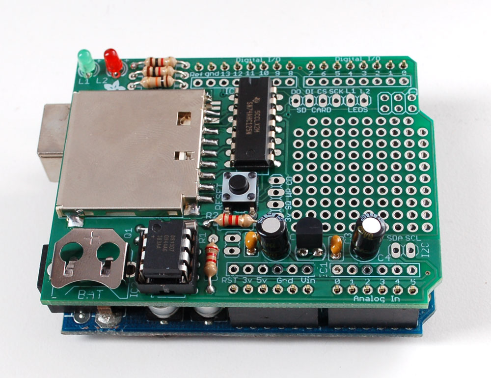
Data logging shield
Here's a handy Arduino shield: we've had a lot of people looking for a dedicated and well-designed data logging shield. We worked hard to engineer an inexpensive but well-rounded design. Not only is it easy to assemble and customize, it also comes with great documentation and libraries.
You can get going within an hour - saving data to files on any FAT16 or FAT32 formatted SD card, to be read by any plotting, spreadsheet or analysis program. We even have a tutorial on how to use two free software programs to plot your data. The included Real Time Clock timestamps all your data with the current time, so that you know precisely what happened when!
- SD card interface works with FAT16 or FAT32 formatted cards. 3.3v level shifter circuitry prevents damage to your SD card
- Real time clock (RTC) keeps the time going even when the Arduino is unplugged. The battery backup lasts for years
- Included libraries and example code for both SD and RTC mean you can get going quickly
- Prototyping area for soldering connectors, circuitry or sensors.
- Onboard 3.3v regulator is both a reliable reference voltage and also reliably runs SD cards that require a lot of power to run

step 1Overview
This page will run through the schematic, explaining whats going on and why picked the parts we did!
Here's the 'big picture' schematic for reference:
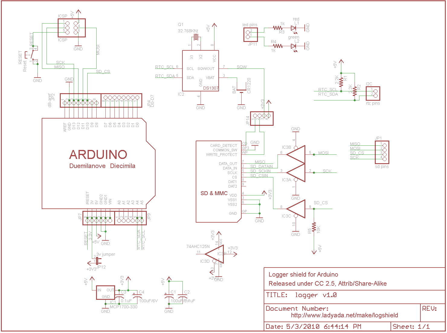
There is a small power supply on the board for generating 3.3V @ 250mA. We don't use the 'built in' 3.3v regulator on the Arduino because its only guaranteed up to 50mA and some SD card need a lot of power when writing. This supply is nice and steady, we can use it as an analog reference too! We have two sets of bypass caps to try and keep both 5V and 3.3V supply nice and clean - the 100uF ones are for the low frequency noise and 0.1 for higher frequency
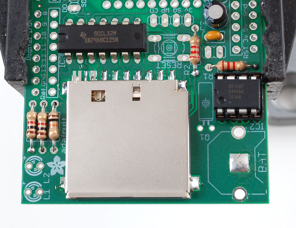
The real time clock is the DS1307 from Maxim, which has a battery backup (CR1220) and communicates with the Arduino via i2c (the SCL and SDA lines). i2c requires pullup resistors on the clock and data lines, which you see as R1 and R2. 2.2K are good values, but if you're in a bind, 1.0K to 10K will probably work fine.
The RTC requires a single 12.5pF load crystal at 32.768 KHz, Q1 - this is how it keeps time
There are also two LEDs for general purpose blinkin' - we like to use them to tell when the SD card is being written to.
SD card interface:
The SD card holder is connected to the Arduino through a buffer IC3. The buffer is a level shifter, converting the 5V signals into 3.3V ones which are safe to use. (For some cards its OK to use 5V signals but you risk the card being permanently damaged!) There is a pull up on the CS line so that if you program the Arduino with a ISP programmer while theres a card in, you wont scramble it.
There are two 'unused' lines from the SD card - Card Detect is shorted to ground when a card is inserted. Write Protect is shorted to ground when a card with the safety switch flipped is inserted.
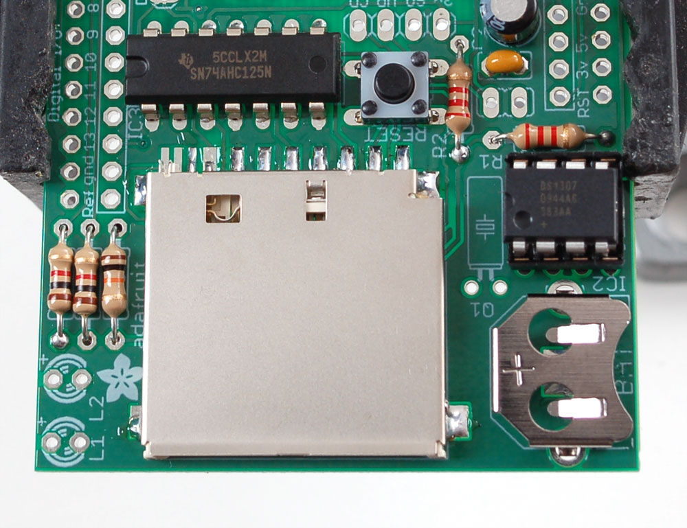
There is also a RESET button, handy when you want to start the Arduino over!

step 2Tools and Preparation
This kit is pretty simple, but you should follow these steps fully so that you'll have no problems!
Learn to solderLearn how to solder with tons of tutorials!
There are a few tools that are required for assembly. None of these tools are included. If you don't have them, now would be a good time to borrow or purchase them. They are very very handy whenever assembling/fixing/modifying electronic devices! I provide links to buy them, but of course, you should get them wherever is most convenient/inexpensive. Many of these parts are available in a place like Radio Shack or other (higher quality) DIY electronics stores.
I recommend a "basic" electronics tool set for this kit, which I describe here.
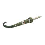 | Soldering iron. One with temperature control and a stand is best. A conical or small 'screwdriver' tip is good, almost all irons come with one of these. A low quality (ahem, $10 model from Radioshack) iron may cause more problems than its worth! Do not use a "ColdHeat" soldering iron, they are not suitable for delicate electronics work and can damage the kit (see here) Check out my recommended basic soldering iron and where to buy. |
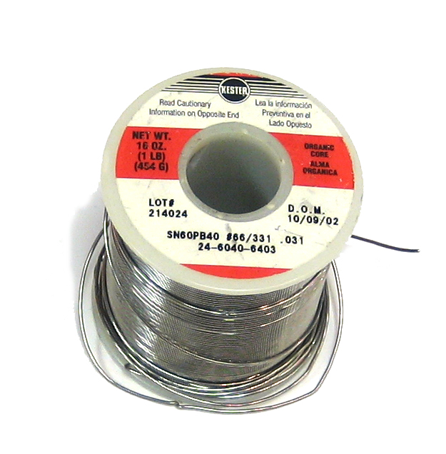 | Solder. Rosin core, 60/40. Good solder is a good thing. Bad solder leads to bridging and cold solder joints which can be tough to find. Don't buy a tiny amount, you'll run out when you least expect it. A half pound spool is a minimum. |
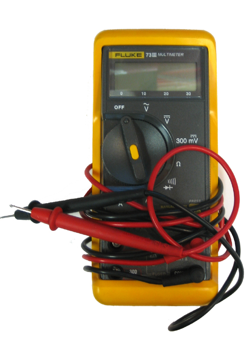 | Multimeter/Oscilloscope A meter is helpful to check voltages and continuity. |
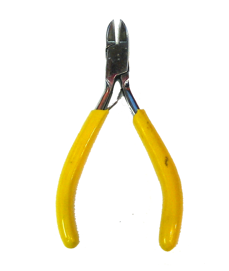 | Flush/diagonal cutters. Essential for cutting leads close to the PCB. Check out my recommended basic diagonal cutters and where to buy. |
 | Desoldering tool. If you are prone to incorrectly soldering parts. Check out my recommended basic desoldering tool and where to buy. |
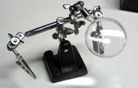 | 'Handy Hands' with Magnifying Glass. Not absolutelynecessary but will make things go much much faster. Check out my recommended basic 3rd hand tool and where to buy. |
| Good light. More important than you think. |

step 3Check the Parts List
Bill of Materials
Image | Name | Description | Part information | Qty | |||||||
|---|---|---|---|---|---|---|---|---|---|---|---|
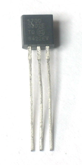 | IC1 | 3.3V linear voltage regulator, 250mA current | MCP1700-3302E/TO | 1 | |||||||
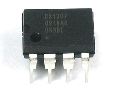 | IC2 | Real time clock | DS1307 | 1 | |||||||
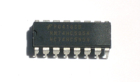 | IC3 | Level shifter for SD card If you don't have this part, you've probably got a v1.0 kit. See the parts list below | 74AHC125 | 1 | |||||||
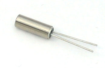 | Q1 | 32.768 KHz, 12.5 pF watch crystal | 1 | ||||||||
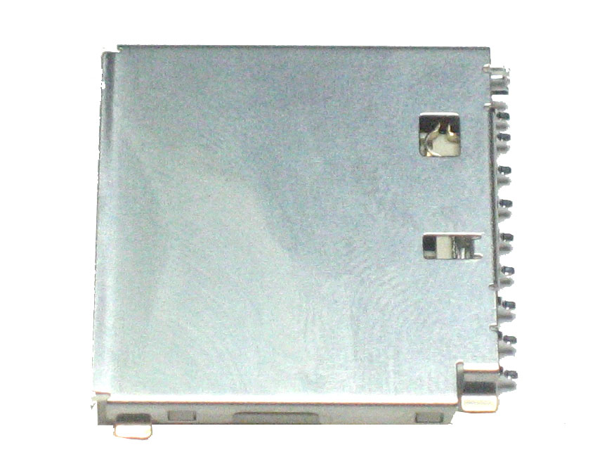 | SD/MMC card holder |
| 1 | ||||||||
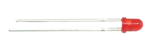 | LED1 | 3mm Red LED | Generic | 1 | |||||||
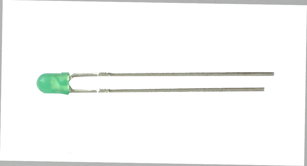 | LED2 | 3mm Green LED | Generic | 1 | |||||||
| R5 | 1/4W 5% 10K resistor Brown, Black, Orange, Gold | Generic | 1 | |||||||
| R3, R4 | 1/4W 5% 1.0K resistor Brown, Black, Red, Gold | Generic | 2 | |||||||
| R1, R2 | 1/4W 5% 2.2K resistor Red, Red, Red, Gold | Generic | 2 | |||||||
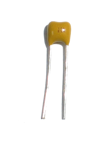 | C2, C3 | 0.1uF ceramic capacitor (104) Looks deceptively like the 0.01uF ceramic capacitor! | Generic | 2 | |||||||
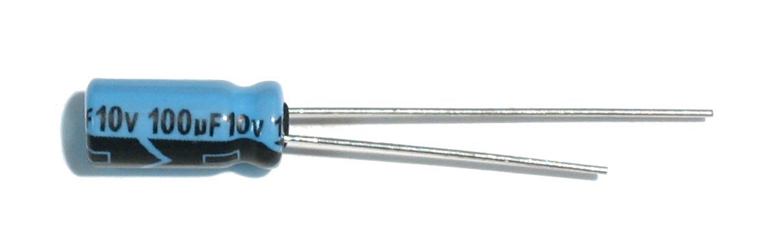 | C1, C4 | 100uF / 6V or greater capacitor | Generic | 2 | |||||||
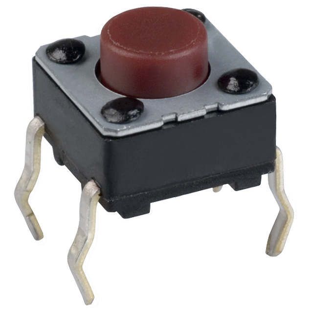 | RESET | 6mm tactile switch | B3F-1000 | 1 | |||||||
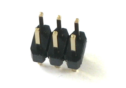 | ICSP | 6-pin ICSP header | Generic | 1 | |||||||
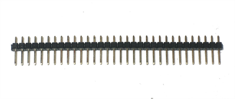 | 36 pin male header (1x36) | Generic | 1 | ||||||||
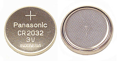 | BATT | 12mm 3V lithium coin cell | 1 | ||||||||
 | BATT' | 12mm coin cell holder | 1 | ||||||||
| PCB | Circuit board | 1 |


step 4Solder the kit!
Solder together the kit
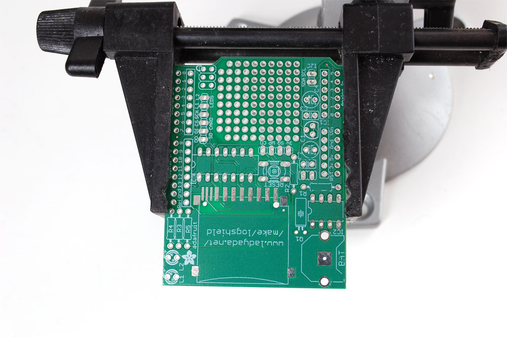 | Prepare to assemble the kit by checking the parts list and verifying you have everything! Next, heat up your soldering iron and clear off your desk. Place the circuit board in a vise so that you can easily work on it |
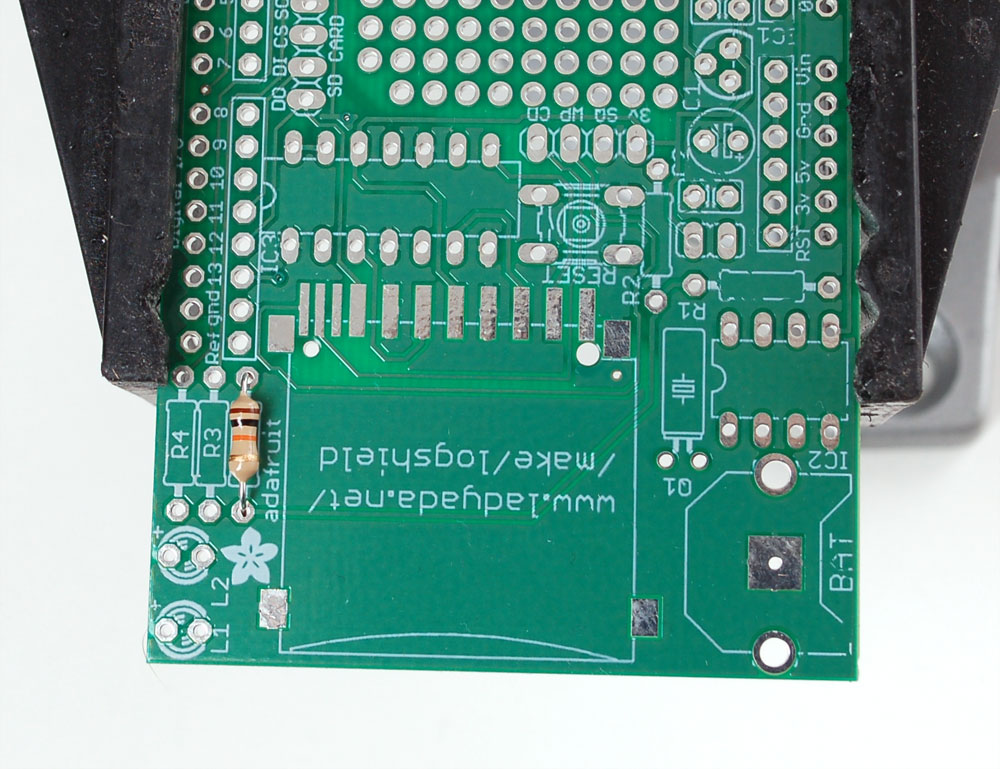
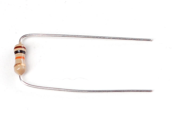 | The first part we're going to solder is a 10K resistor. The 10K resistor is striped Brown Black Orange Gold. Bend the resistor into a staple as shown. |
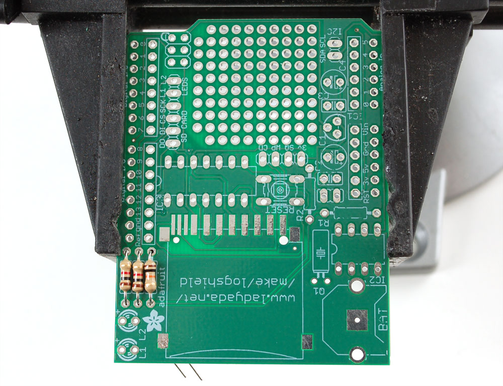
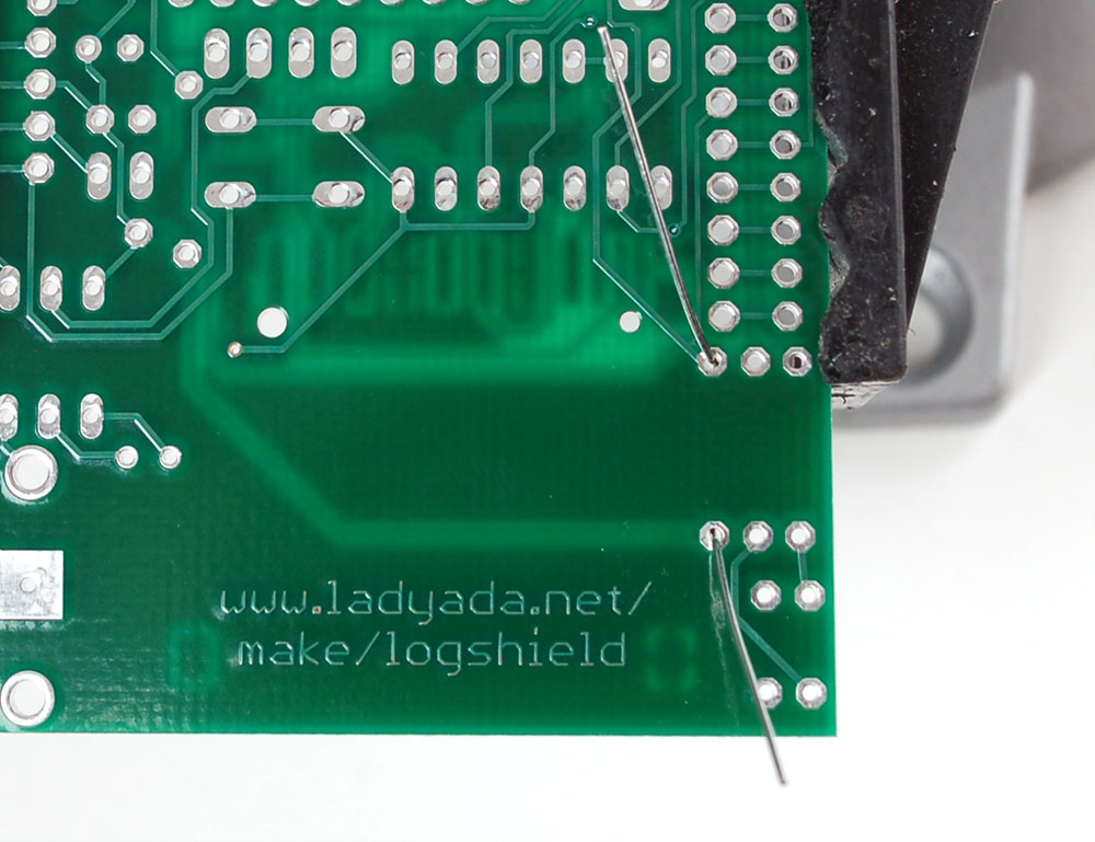
| Place the resistor in the location marked R5. Resistors do not havepolarity which means you can put it in 'either way' and it will work just fine. Bend the wire legs out so that the resistor sits flat against the PCB. This resistor is necessary to keep the SD card deactivated when not in use - this prevents accidental writes to the card that could scamble it! |
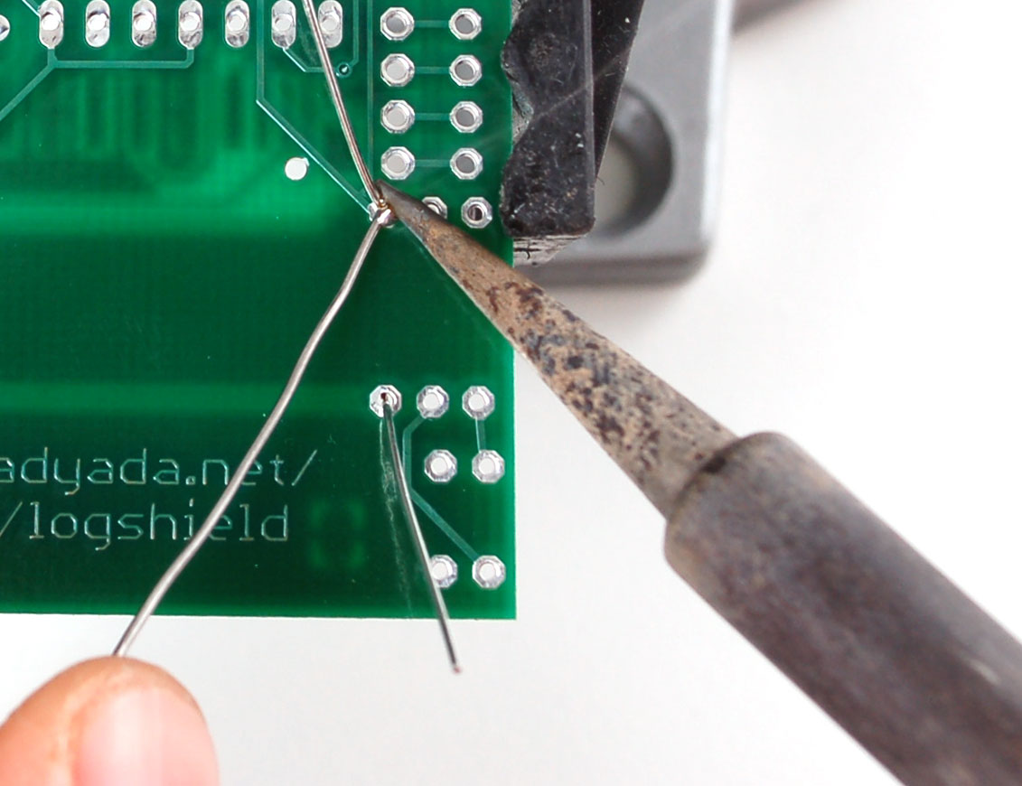
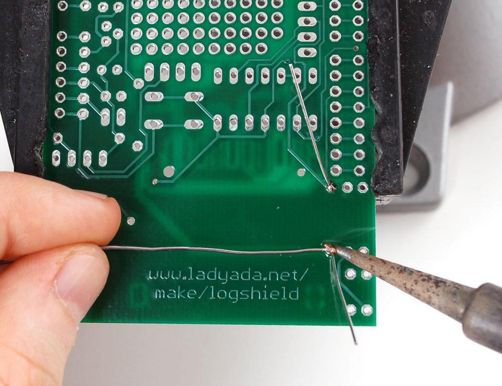
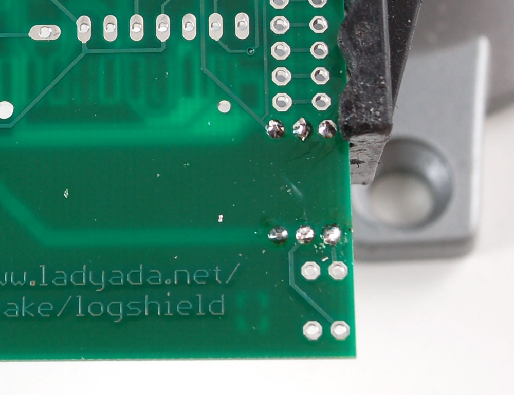
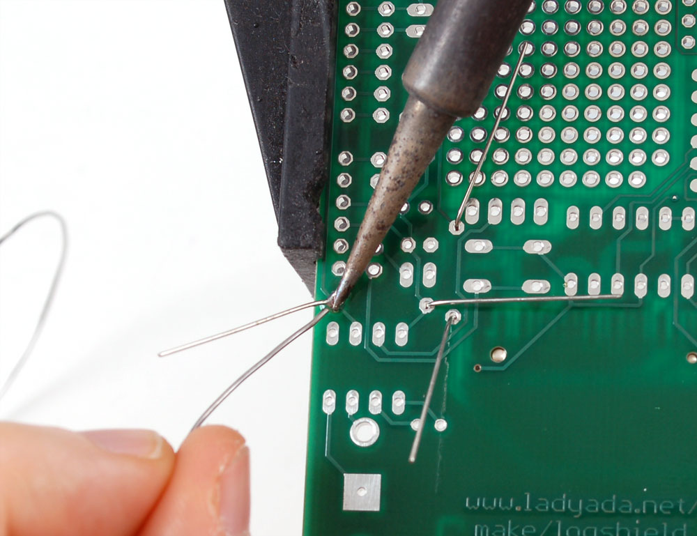
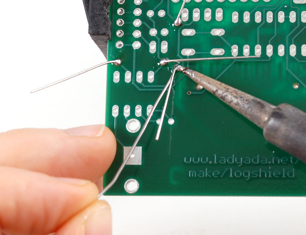
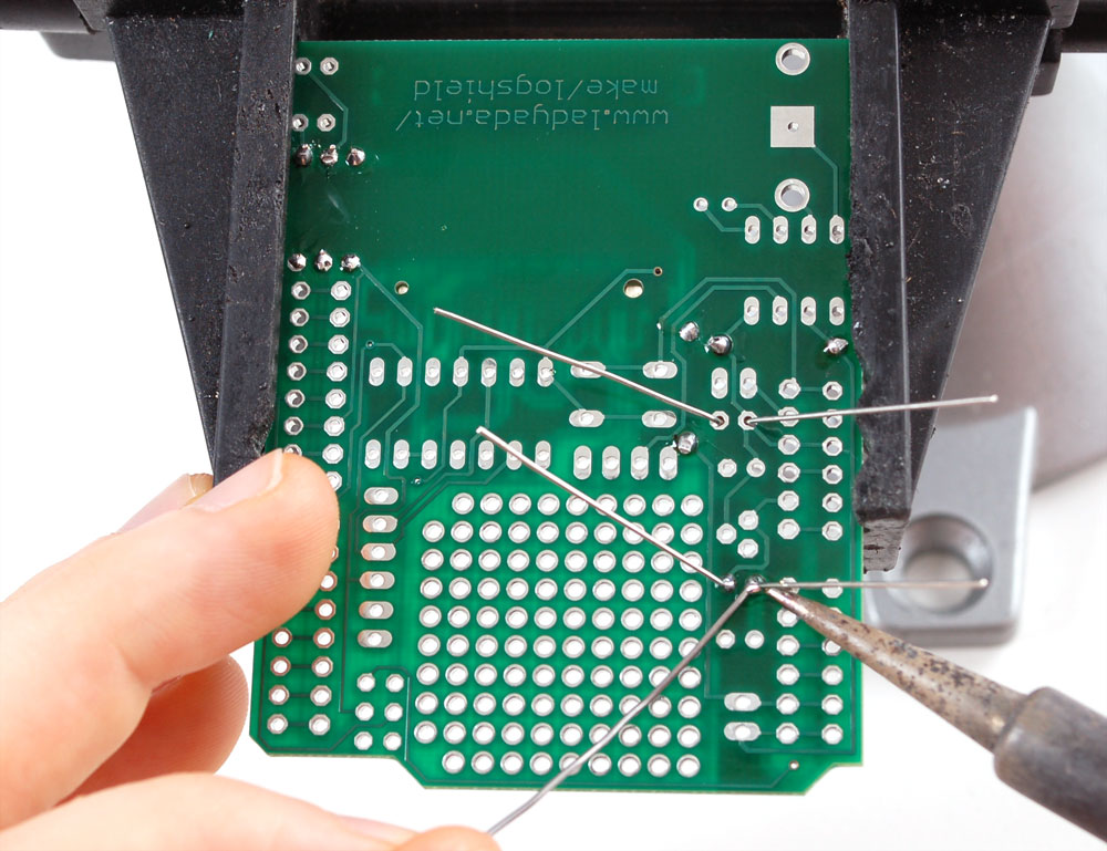
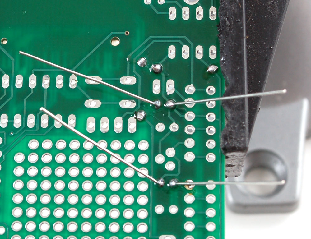
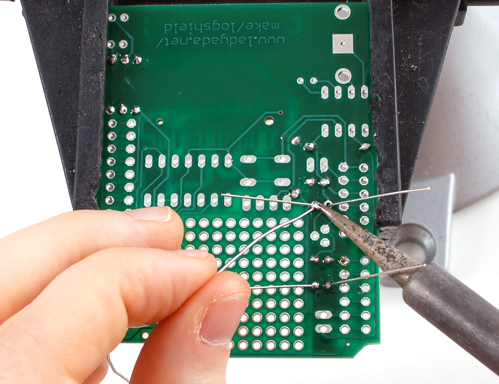
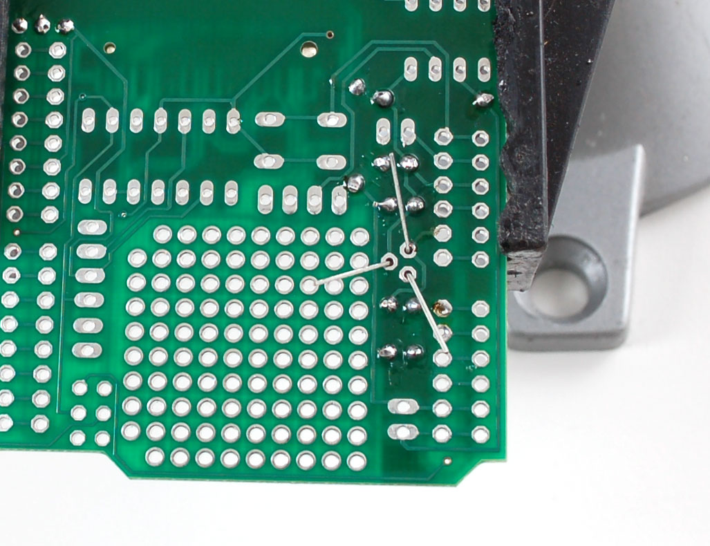
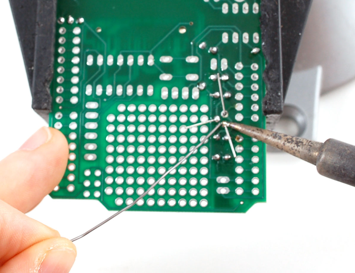
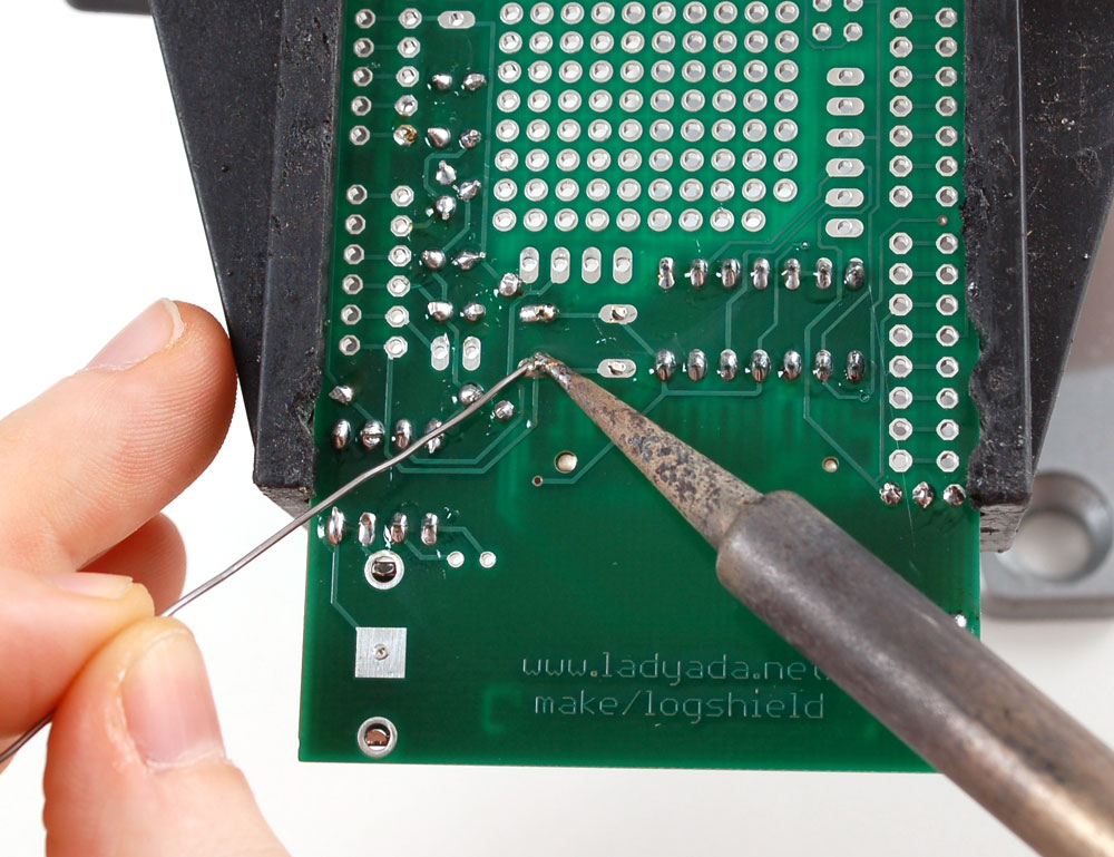
| Turn the PCB over. Using your soldering iron tip, press and heat both the pad (the silver ring around the hole) and lead (wire) at the same time for 2 or 3 seconds. Then poke the end of the wire into create a nice solder joint. Do this for both leads. |
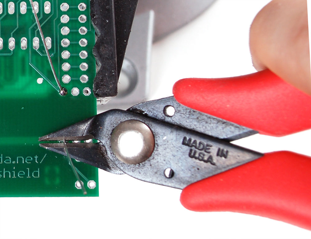
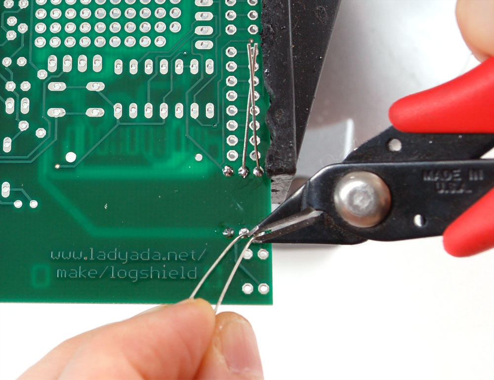
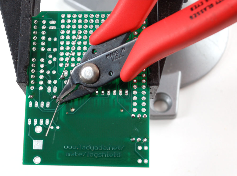
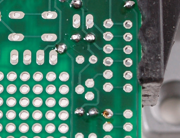
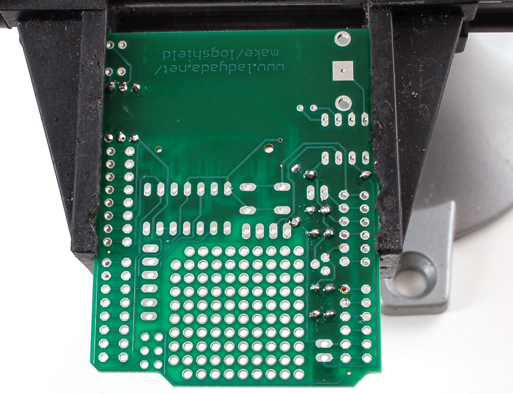
| Using your diagonal cutters, cut off the long leads just above the solder joint. |
 | The next two resistors are 1.0K - their color strips are Brown Black Red Gold. Bend and place them in the slots labeled R3 andR4 These resistors set the brightness of the two indicator red/green LEDs |
| Flip over the PCB and solder the 2 resistors. |
| Clip the two resistors' leads |
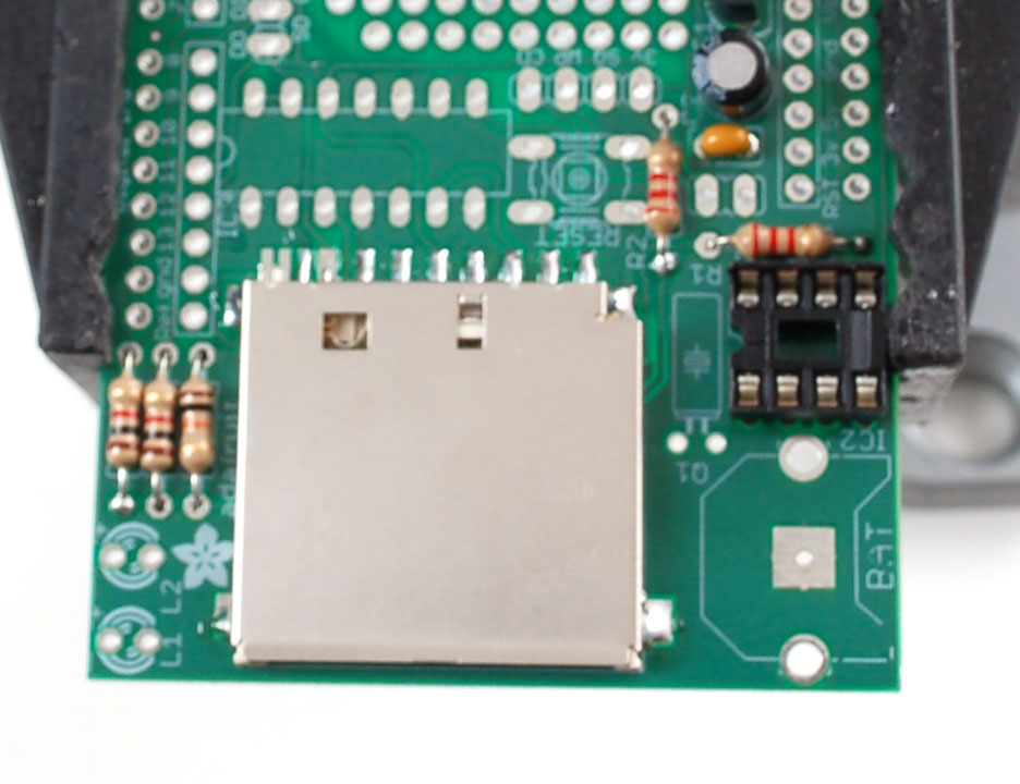
 | Once you are feeling comfortable with the resistors, lets do the SD card holder. The holder is surface mount (there are no wires that go through the board) but the spacing is very generous, so it wont be difficult. The holder has two bumps that 'snap' into place on the PCB. Make sure that the bumps are engaged and the holder is sitting flat. |
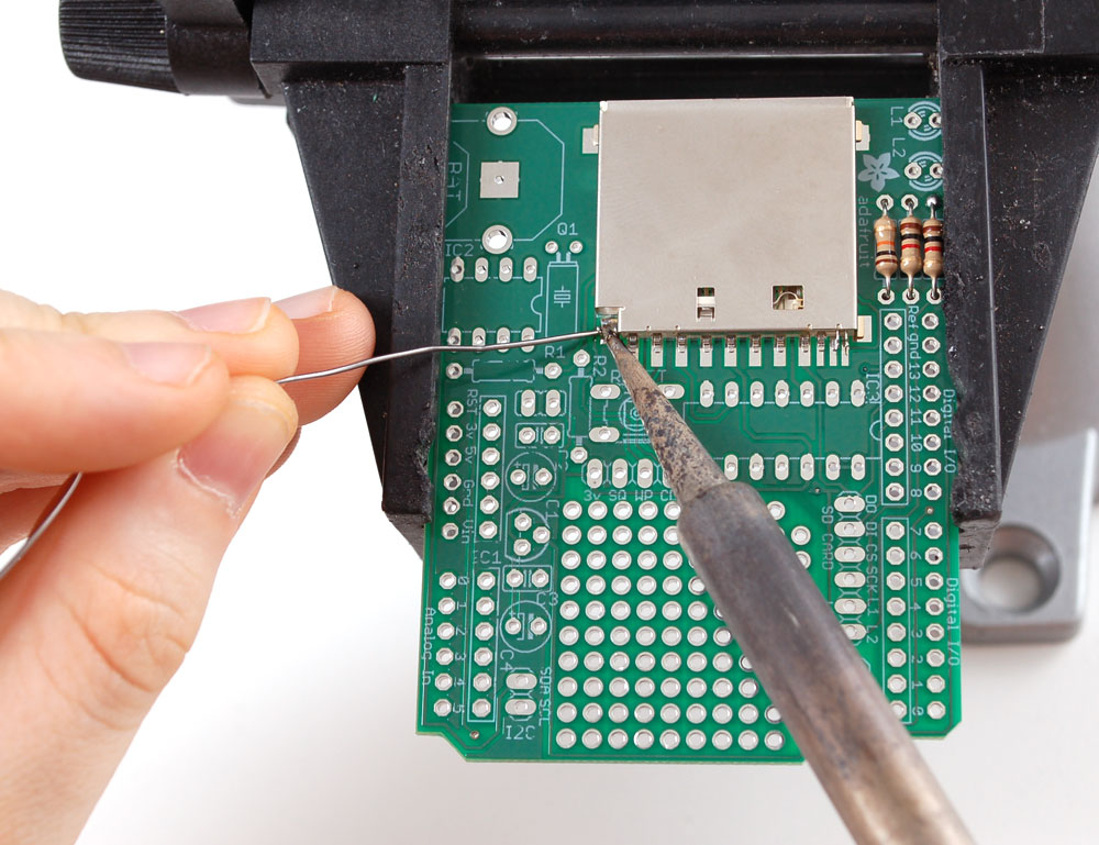
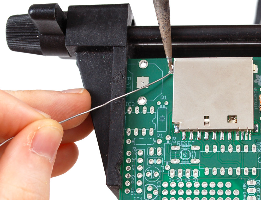
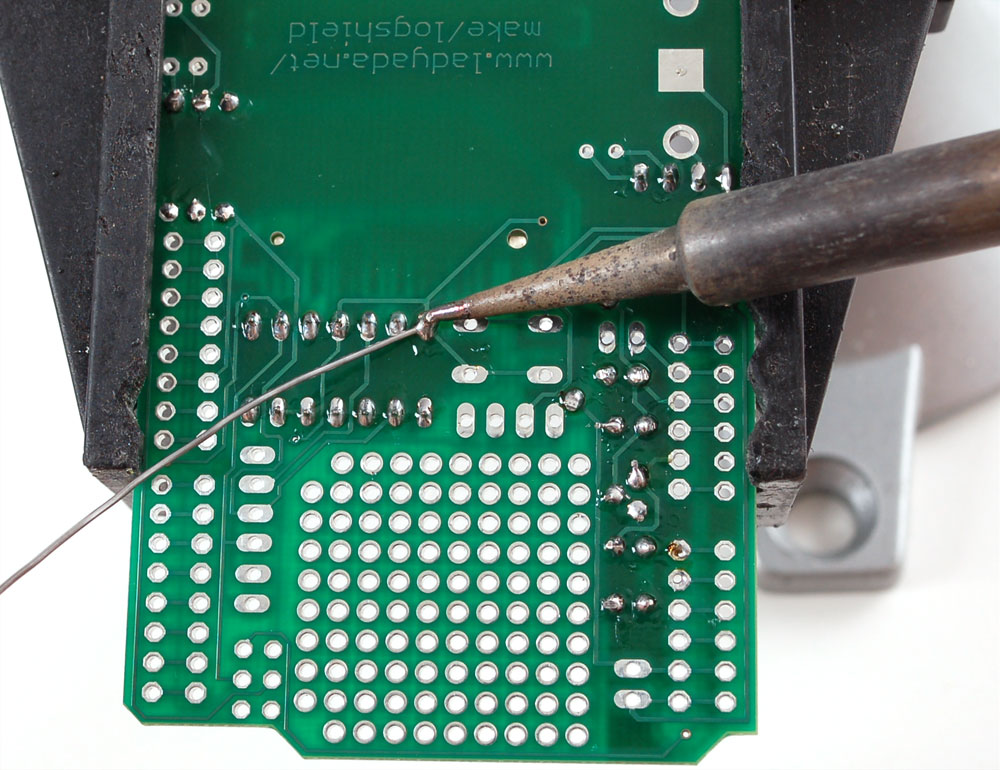
| The first step to soldering the holder is to 'tack' it in place. On the sides are 4 large tabs. Heat both the pad and tab together for 3 seconds and solder the tab down. Repeat for all 4 tabs. When you're done you shouldn't be able to move the holder. |
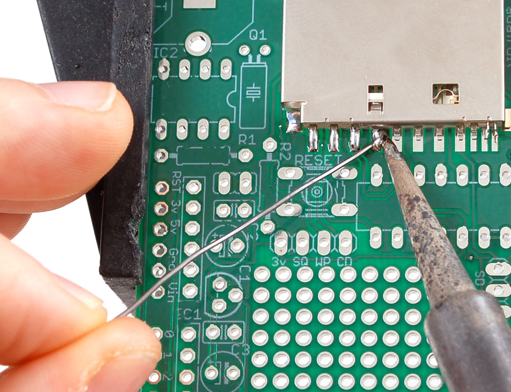
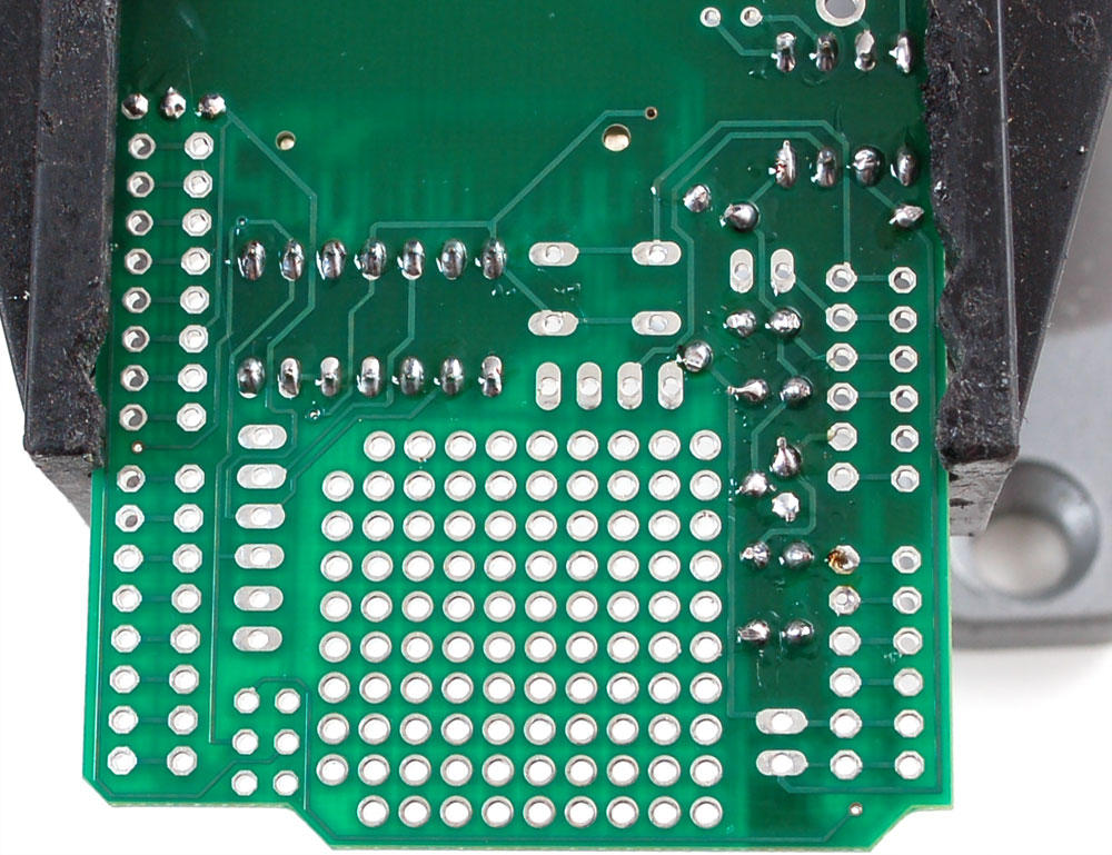
| Next, solder the 7 large leftmost pins of the holder to the corresponding pads. Use a sparing amount of solder so that you wont end up bridging two pins by accident. If you aren't skilled at SMT soldering, you can simply skip the last three smaller pins, they're not at all necessary |
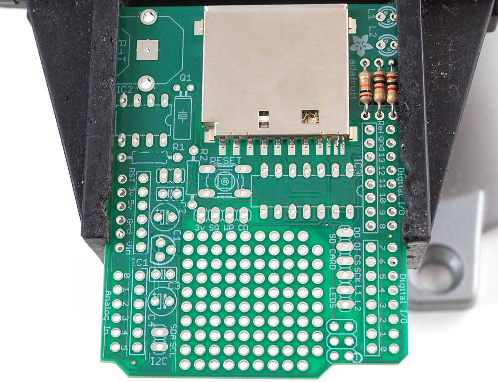
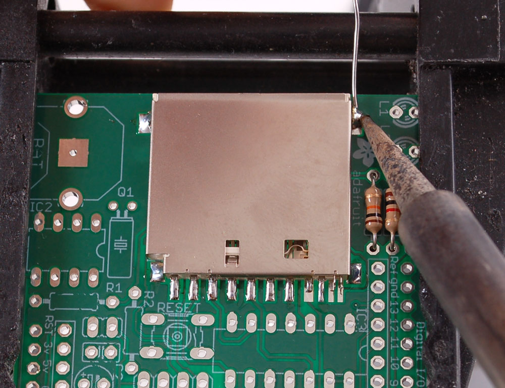
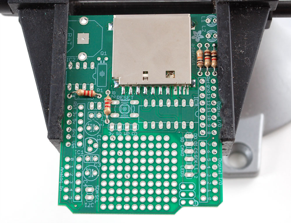
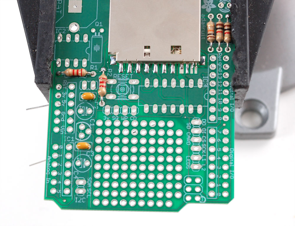
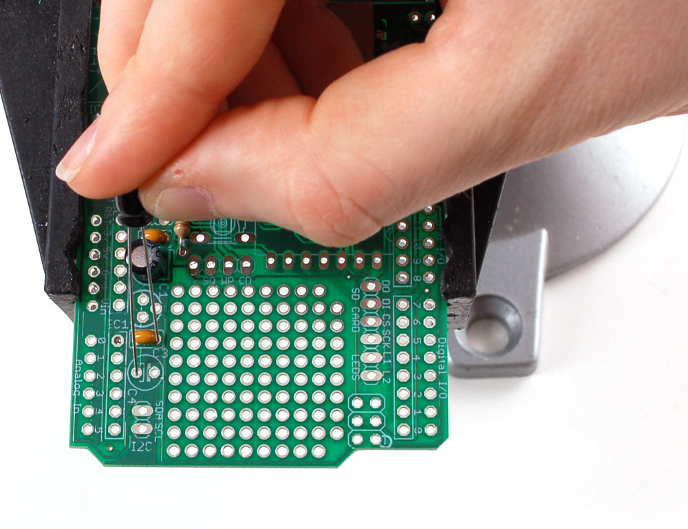
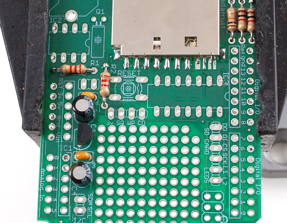
| We will now solder in the two 2.2K resistors (Red Red Red Gold) into the two slots labeled R1 andR2 These two resistors are used by the RTC chip data lines. |
| Solder the resistors using your now-expert resistor soldering skills |
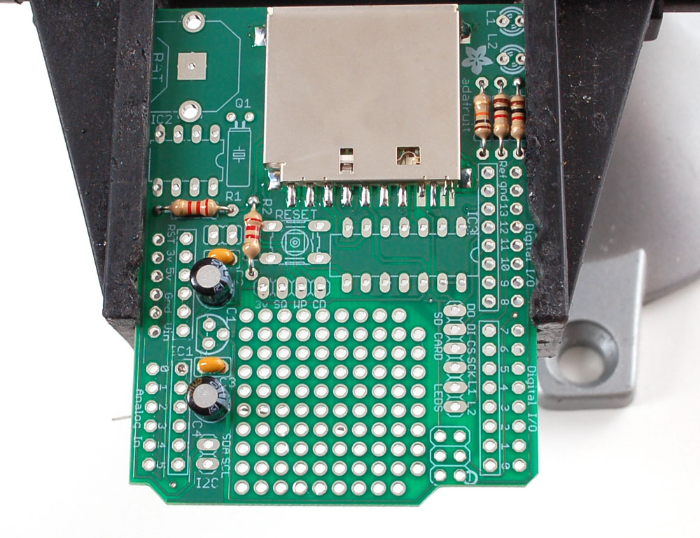
| Next we will install the two yellow ceramic capacitorsC1 and C3. Ceramic capacitors are not polar so they can be inserted either way and will work fine. Bend out the leads like the resistors to keep them flat against the PCB |
| Place, solder and clip the capacitors. |
| Next are the electrolytic capacitors C1 and C4. Electrolytic capacitors are polarized and must be placed correctly. The longer lead of the capacitor is the positive (+) lead. Make sure this lead is placed in the hole marked with a +. Look carefully before soldering to make sure you got this part right!
|
| Solder and clip |
| Next we will solder in the 3.3v regulator. The regulator is in a TO-92 package, with a semi-cylindrical plastic part and three legs. Insert it into the location marked IC1. Because of the way the pads are layed out, the regulator wont sit flat against the PCB. Thats OK, it should stick up a little bit. Make sure the flat side of the package matches the outline on the silkscreen Solder and clip the three leads |
| Next we will place and solder the 8 pin socket. The socket is for protecting the clock chip and making it easy to insert and remove. Unfortunately, RTCs often shouldnt be removed which means that placing this part is not always preferrable. If the loggershield is going to be used in a place where the chip may get knocked out, you may want to skip the socket and just solder the chip in The socket has a little notch in one end. That notch should match the one in the picture silkscreened onto the circuit board. This will help you place the chipin properly later. In this photo its on the LEFT You may need to solder one pin of the socket while holding it it in with a finger (or tape) as the legs aren't long enough to be bent while in place. |
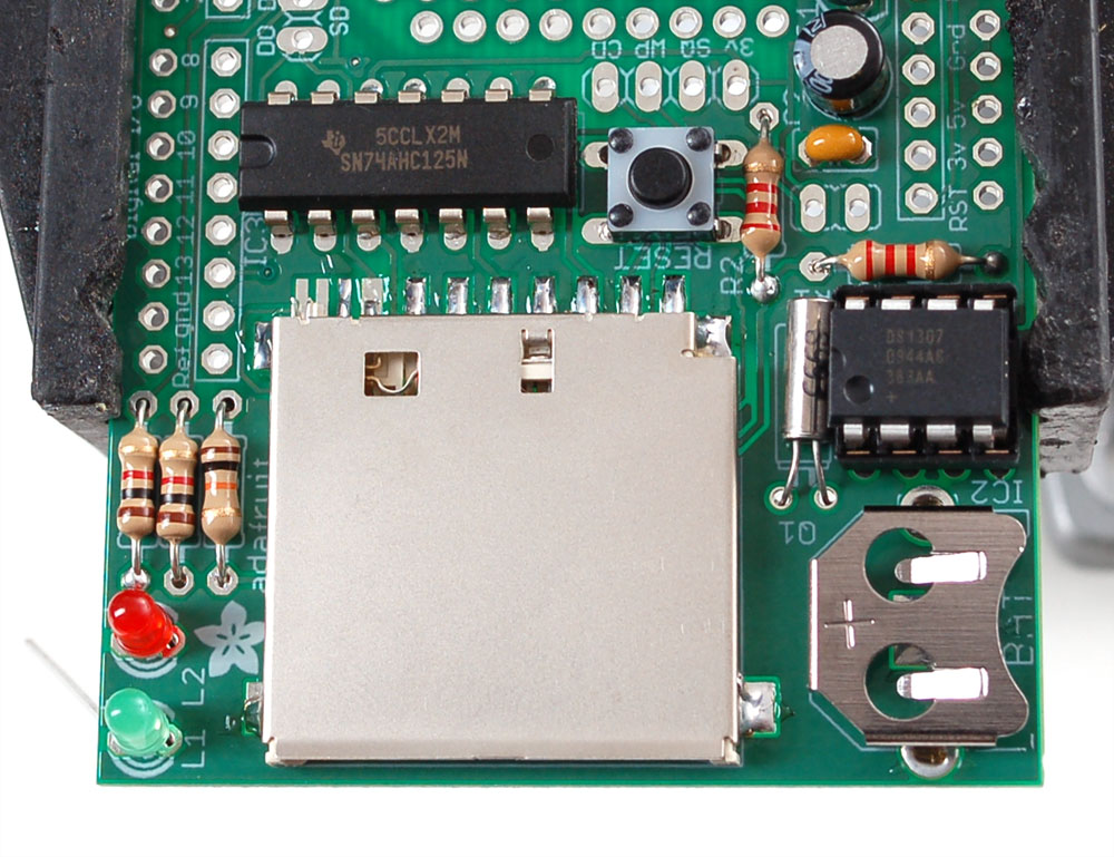
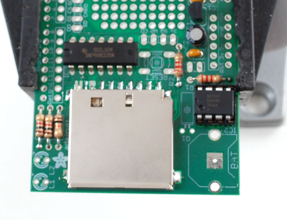
| Now you can place IC2the DS1307 RTC chip into the socket by gently bending the pins in so that they line up with the socket and the dot and notch in the chip are on the same side as the socket notch. The RTC is what keeps time when the power is out, its a very very very low power microcontroller and crystal that will keep time for years on a tiny coin cell. This way you can mod your clock with ease and not have to reset it after power loss. The next chip IC3 is the CD4050 which is the 3.3V buffer chip that converts the 5V signals from the Arduino to the 3.3V SD-card IC's must be placed a certain way, or they dont work. Make sure you get this right because if the part is in wrong its a real pain to fix! On one end of the chip is a round notch. In this photo its on the right. Make sure this notch matches the silkscreen underneath where there a similar round notch. In thie photo its on the LEFT Solder in all the pins of the chip |
|
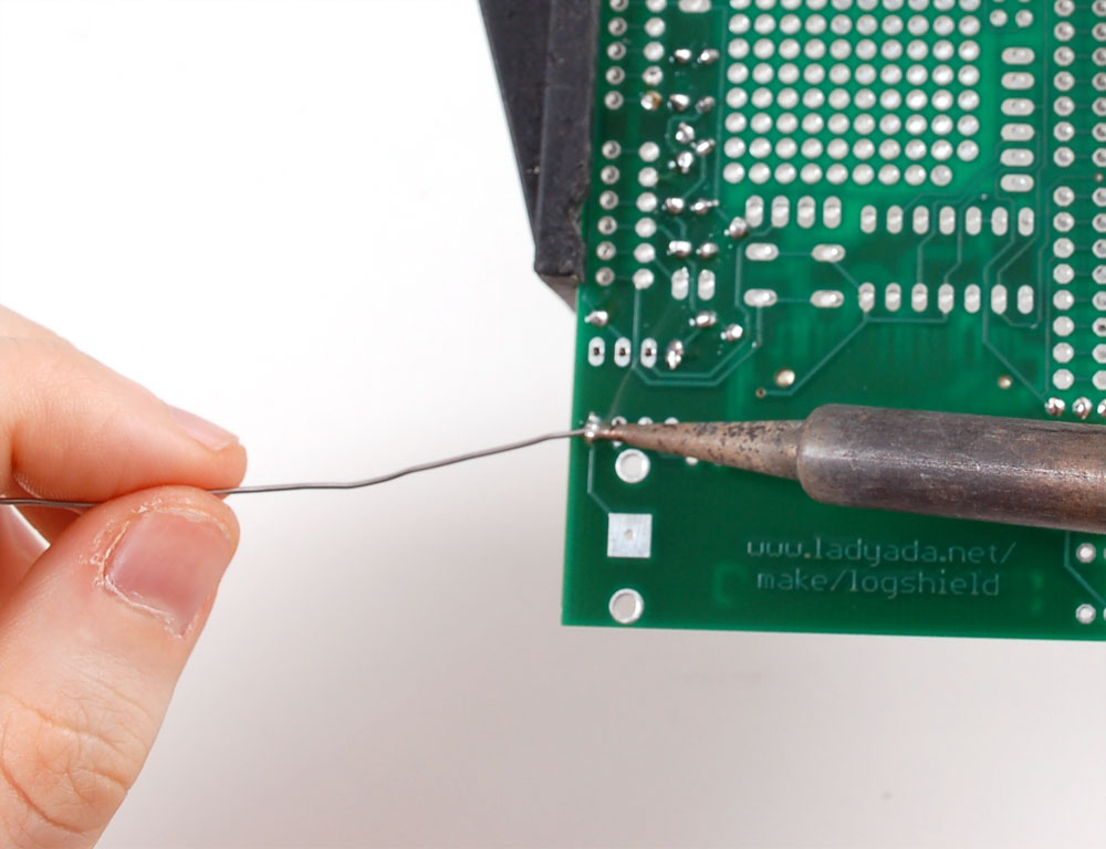
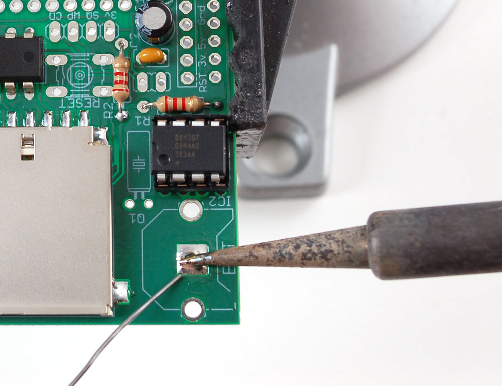
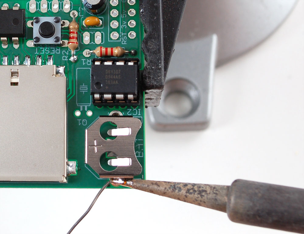
First, melt a tiny bit of solder onto the center tab of the battery holder BAT. This will make good contact with the battery.
|
| Now place the 12mm coin battery holder BATand the 6mm buttonRESET. The button is a symmetric part so it can go in two ways. Line up the metal legs with the holes in the circuit board and snap it in. The button should sit flat against the circuit board. Tack solder one side of the battery holder so it doesnt fall out when you flip over. |
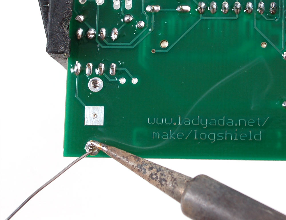
| Now solder the button and battery holder into place. There's nothing to clip. |
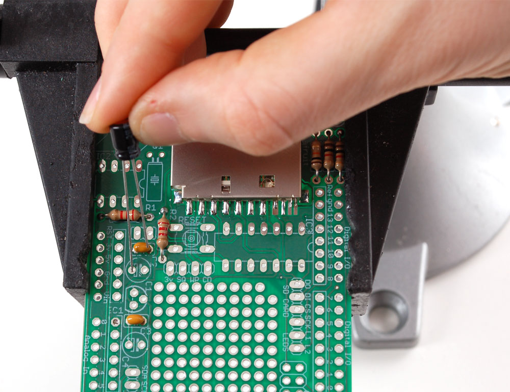
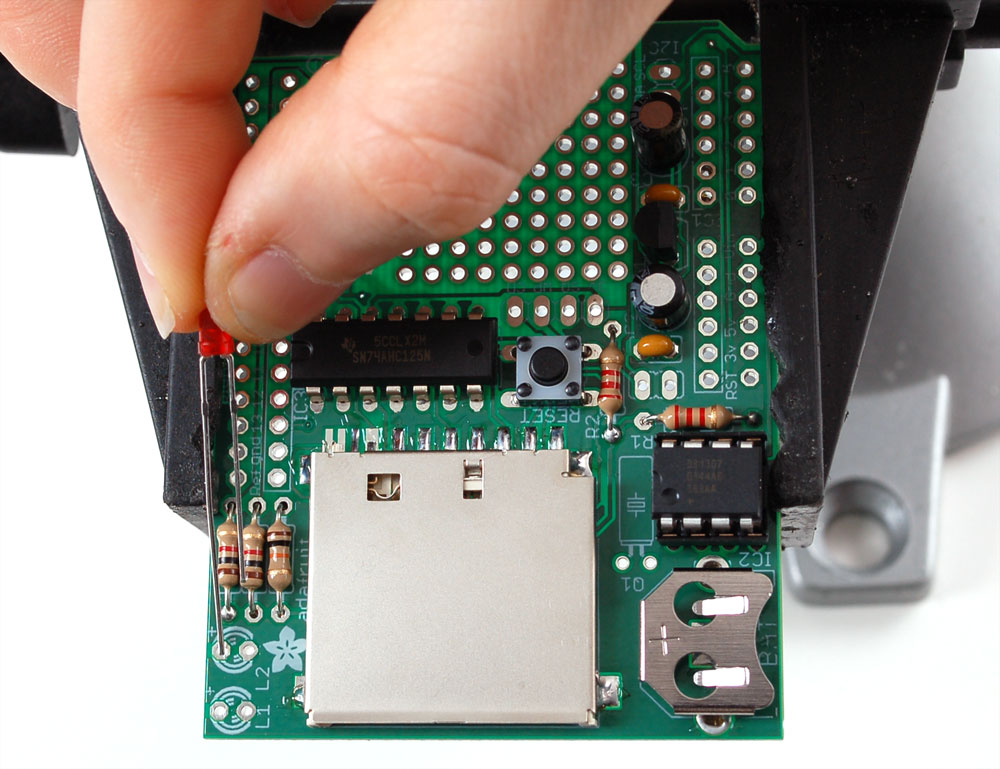
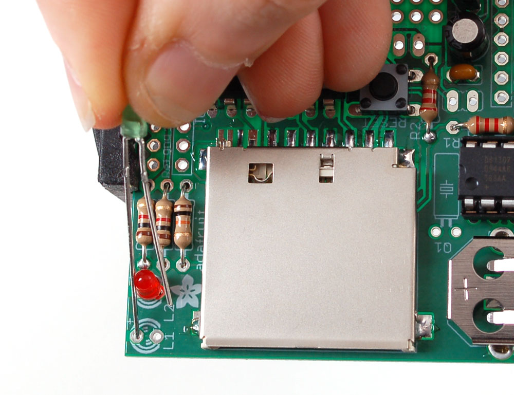
| Next are the red and green indicator LEDs. LED stands for Light Emitting Diode, and they must be placed correctly or they wont work. To make sure the LEDs are installed properly, check that there is a lead that is longer than the other. This lead is the positive (+) lead. Make sure that this lead goes into the hole marked with a + on the PCB silkscreen, as shown. |
 | Next is the 32.768 KHz watch crystal Q1. The crystal is the same as whats in your 'quartz' watch or clocks - it is the thing that ticks to tell time. The crystal is nonpolar. |
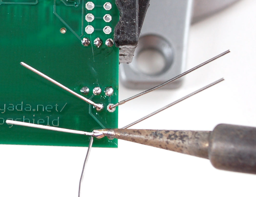
| Solder and clip the two LEDs and crystal |
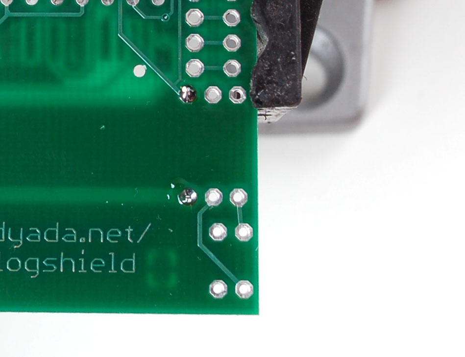
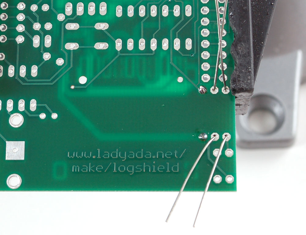
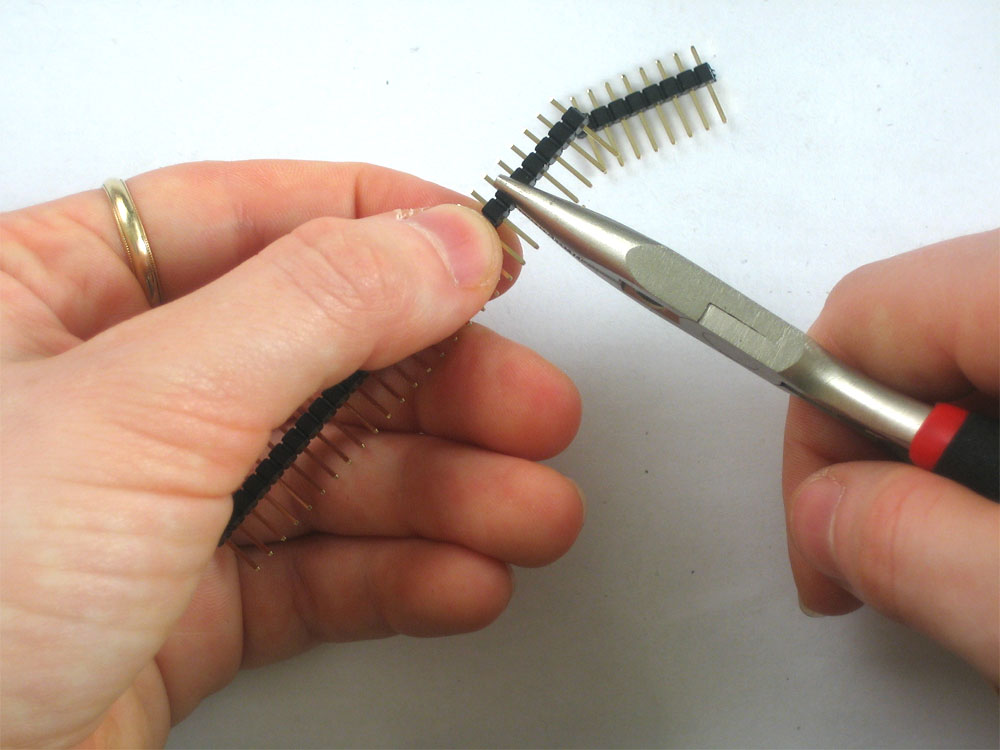
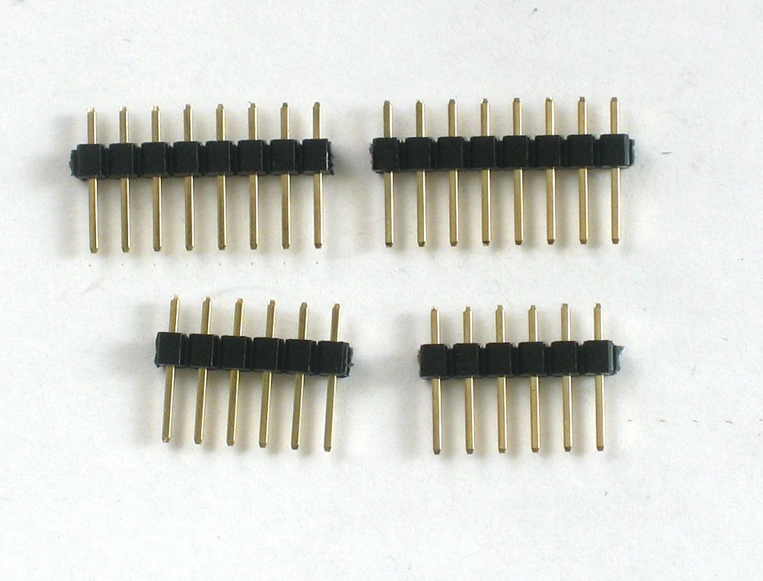
| Next, break the 36-pin header strip into smaller sections so that the shield can be placed on the Arduino. You can use pliers or diagonal cutters. You will be able to perfectly snap the long strip into 2 8-pin strips, and 2 6-pin strips. |
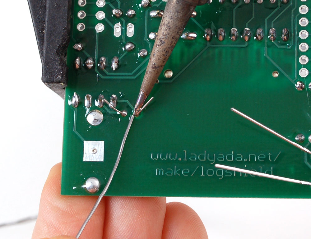
 | Put the long ends of the male header in to the female header on the Arduino, as shown |
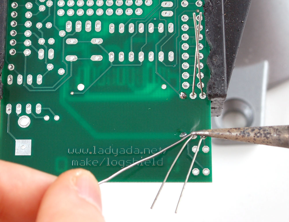
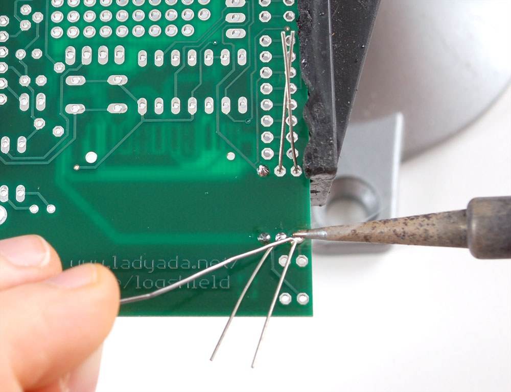
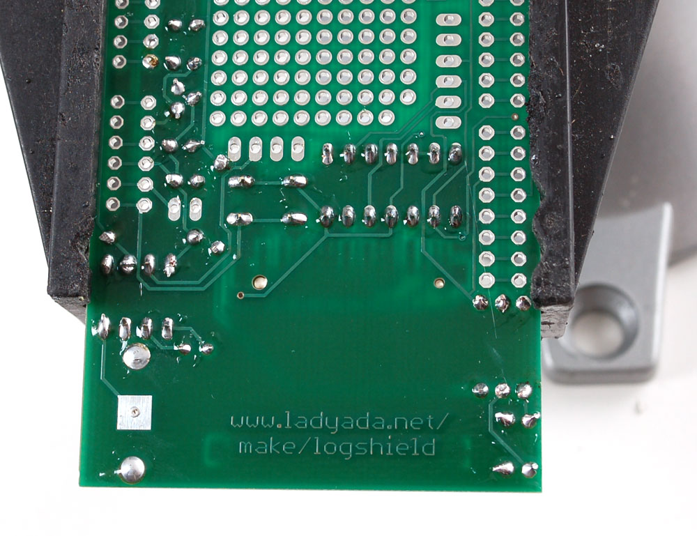
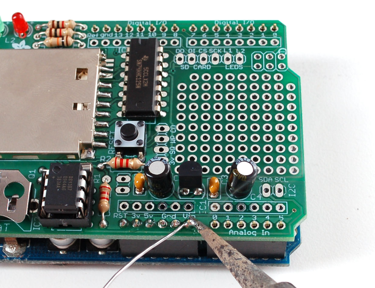
| Put the shield on top of the Arduino, so that the male header aligns with the solder holes. Solder every pin of the male header. Keep the shield on the Arduino to make the job easy. Once you're done, you can remove the shield from the Arduino. |
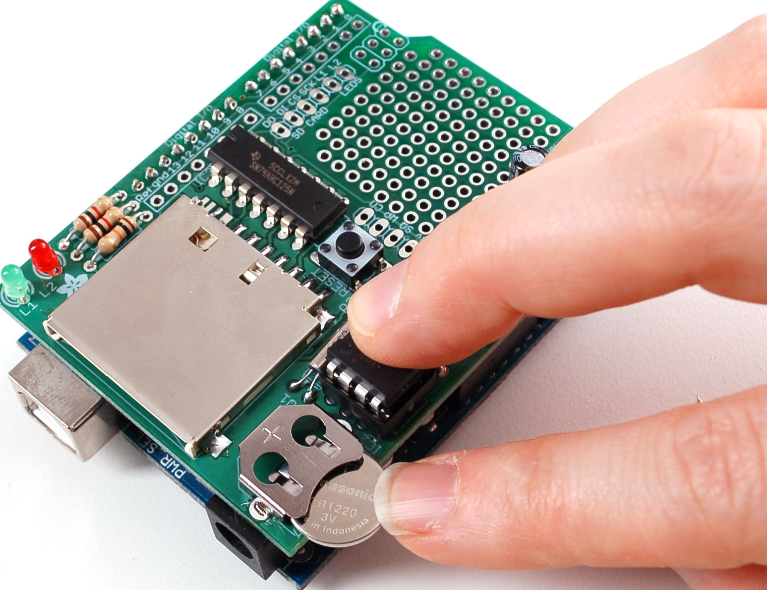 | The last assembly step is to insert the battery. The flat side goes up. It will last years so you will only have to do this once. |
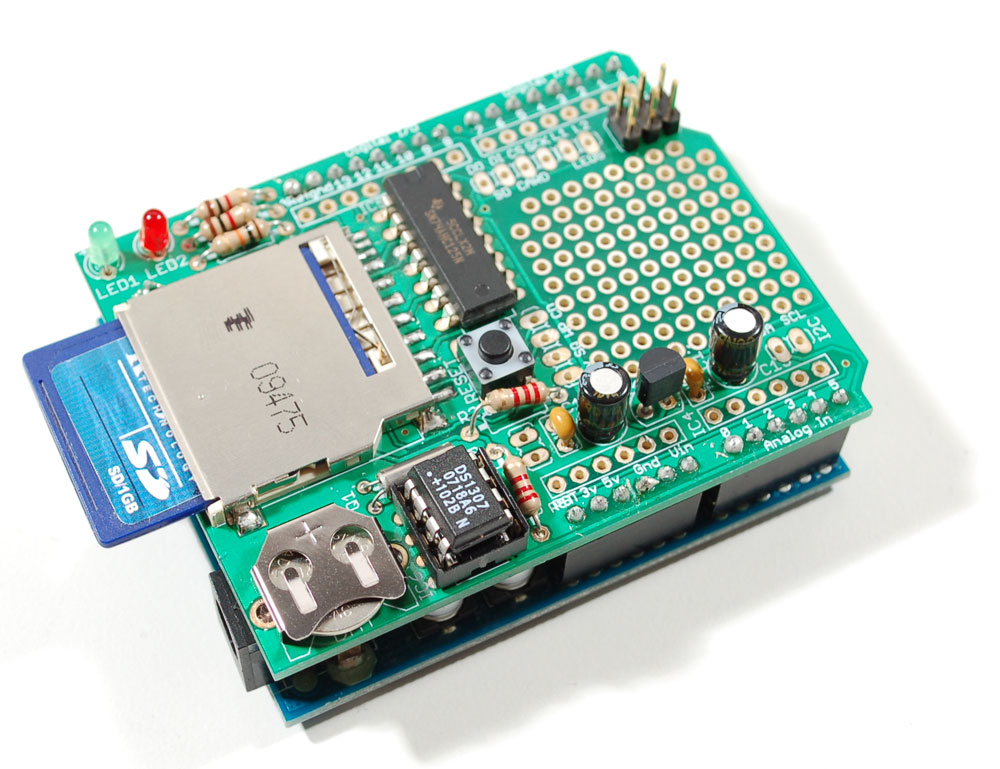 | You're done! Now you can get an SD card and start reading the usage documentation! |


step 5Use it!
Get 'er loggin'
Once you have your shield soldered up you can use the RTC and SD card for logging time-stamped data.
- The Real Time Clock (RTC) - what it is and how to use it!
- The SD card - Preparation for writing the the SD card
- Fridgelogger - An example project showing (nearly) everything you'll need to know about getting data, and writing it to the SD card
- A detailed walkthrough of the final sketch used in the fridgelogger - a really good idea to read for information on why things are done
step 6Download files
Arduino libraries
- SDFATlib - a FAT16/FAT32 SD card library perfect for reading & writing from SD cards written by fat16lib
- RTClib - a library for getting and setting time from a DS1307 (originally written by JeeLab, our version is slightly different so please only use ours to make sure its compatible!) - download the .zip by clicking on Download Source (top right) and rename the uncompressed folder RTClib
For detailed information on installing libraries, make sure to read our tutorial
These files are Creative Commons Attribution, Share-Alike - enjoy!
- Download the latest files from GitHub (click on the file name then right-click Raw and select Save as...)
- An image of the v1.0 schematic
- Download the latest Light and Temperature data logger sketch from GitHub
- Logging Test data set
- Overnight Fridge logger data set


