Sunday, June 20, 2010

ARDUINO

Arduino is an open-source electronics prototyping platform based on flexible, easy-to-use hardware and software. It's intended for artists, designers, hobbyists, and anyone interested in creating interactive objects or environments.

Arduino can sense the environment by receiving input from a variety of sensors and can affect its surroundings by controlling lights, motors, and other actuators. The microcontroller on the board is programmed using the Arduino programming language(based on Wiring) and the Arduino development environment (based on Processing). Arduino projects can be stand-alone or they can communicate with software on running on a computer (e.g. Flash, Processing, MaxMSP).
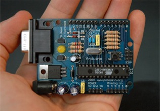
The boards can be built by hand or purchasedpreassembled; the software can be downloaded for free. The hardware reference designs (CAD files) areavailable under an open-source license, you are free toadapt them to your needs.

Arduino received an Honorary Mention in the Digital Communities section of the 2006 Ars Electronica Prix. The Arduino team is: Massimo Banzi, David Cuartielles,Tom Igoe, Gianluca Martino, and David Mellis. Credits


Buy an Arduino Board

Download the Arduino Software


Development: For information on the development of Arduino, see the Arduino project on Google Code. Changes to the software are discussed on thedevelopers mailing list.

Elsewhere: You can find lots of pictures of Arduino projects and workshops in the Arduino tag on Flickr. Related links can be found on the Arduino tag on del.icio.us.


Getting Started

To get started, follow the instructions for your operating system: Windows, Mac OS X or Linux; or for your board:Arduino Nano, Arduino Mini, Arduino BT, LilyPad Arduino,XBee shield. If you're having trouble, check out thetroubleshooting suggestions.

Learning

Examples of how to work with the Arduino language and common electronic components; further readings on thefoundations; information on hacking and extending the Arduino hardware and software; external resources.

Reference

Reference for the Arduino language (see also theextended version); a collection of libraries for working with various types of hardware; a comparison with other prototyping platforms, and information about thecomponents of the Arduino board.

Hardware

Information about the Arduino hardware, including reference designs (EAGLE files).


Blog

General announcements and thoughts from the Arduino team can be found in our blog.

Forum

The multi-lingual forum is the place to go with questions of all kinds.

Playground (Wiki)

We're collecting Arduino knowledge, tutorials, and instructions in the playground wiki.

DIY DCDC Stepup with Max756

Well, after talking about ladyada’s minty boost, I wanted to check out the datasheet for the max756 chip. I wanted to see how she went about designing this circuit, and then wanted to let my readers know the process as well. I figured this would be a good chip to talk about. If you read ladyada’s post.

max756 pinout

From the datasheet, I copied this above pinout diagram of the Max-756 chip. You can see that there are 8 pins on this chip. The above pinout gives a name to each. Now this can be intimidating, but I am going to attempt to discuss each pin, and show you how you can go through this design process.


Pin 1 is a shutdown pin. This is a pin that will power down the chip. When you see a line over the name of a pin it means that it is active when grounded. So we want to give +5v to this to turn the chip on.

Pin 2 is a selector pin. This chip will either do 3.3v output, or 5v output. We want 5v output, so you put this pin low, or grounded. Once again, pay attention to the line above the name. It tells to ground this pin for 5v.

Pin 3 is a reverence voltage pin. I don’t really know the purpose of this, but we don’t need it. Just follow the command, and the schematic. We will put this to ground through a capacitor.

Pin 4 is a low battery detector pin. I don’t care about it, so we can leave it disconnected. You could feasibly use this pin to connect to an LED to show when power is low.

Pin 5 is the low battery input pin. This would be connected to the battery source. When the voltage gets lower than 1.25v, it will tell the LBO to sink low. We aren’t using this because we are using 2 batteries in series to make 3v. You would probably have to use a voltage divider to connect to this. It is not necessary.

Pin 6 is the output pin. It has to be connected like the schematic in the datasheet. This is all pretty much unchanged.

Pin 7 is ground for the circuits inside the chip. It is simply connected to ground.

Pin 8 is LX. It is connected as in the schematic as well.


The above schematic is straight out of the datasheet. The schematic below is from Ladyada. You can see that she basically followed the recommendations with a few changes. She uses the same inductor and zener diode. Ladyada left the LBI unplugged, because she is not using this feature.


Anyway, if you want to do a project, but are afraid of it, then don’t be. If you know of a device or chip that you want to use, then simply go to the datasheet. It will explain all of the pins, and give you a sample schematic. Most of the time, the schematic they give you can be used, or slightly modified. Now Ladyada actually made a circuit board, and etched it herself. You don’t have to do this. You can simply use a breadboard for testing to get your project to work. You can use a simple hole board and solder wires to make up the connection. Not as pretty, but just as functional.

DIY Battery Backup (UPS)

I just recently talked about me starting a saltwater reef aquarium. A lot of time and money goes into starting such a device, and the rewards are great. There is one problem though with having a piece of the ocean sitting in your living room. You have to have a constant supply of electricity. (I have actually found that even on my little 20 gallon tank, that it cost about $25/month to run.) Anyway, if the power cuts off for more than 4-5 hours, it could have devastating results on the poor inhabitants. I almost feel a moral obligation to not let that happen.


I had to start thinking of what I would do in case of a power outage. The oxygen saturation in a saltwater aquarium is much less than that of a freshwater, and if the water stagnates, it can have devastating effects. I also live in a hurricane zone, so that could be a disaster. The obvious solution is to get a generator. This would work for any long term outages. But what happens when the power goes off at 8AM, and you don’t come home for 9 hours?

I thought about getting a battery backup UPS system for a computer. I quickly found that they are very expensive, and don’t contain enough energy to last very long at all. I need at least my main circulating pump to run, and I want it to run for up to 24 hours. The first thing I did was go buy a 13$ battery back up air pump that plugs into the electricity, and turns on if the power is cut. This would at least keep some of the oxygen levels up, and was a quick and cheap fix.

The next thing which I have not built yet because I don’t have the time or money is to build my own battery backup. The design of one is relatively straight forward. All you need is a marine deep cycle battery, which will allow for multiple charges and discharges. I need a trickle charger to always keep the battery topped off, and I need a power inverter. I simply plug the circulating pump into the inverter, and it will run off the battery.

Now that doesn’t make much sense. I need a way of detecting if the electricity is on or off.

diy-backuppower-circuit.gif

All you realy need for that is a double pole double throw switching relay. You connect the coil to the electricity in the wall. If the power is on, the switch will swing one way, and if the power is off, it will swing the other way. Then you connect the “on” switch straight to the electricity. When the power is connected, the pump will be plugged in, and will get its power from the outlet. You also will connect the “off” switch to the power inverter. If the power is cut, the relay will change, and your pump will continue to run off of the battery power through the inverter. You simply buy a nice charger that will turn itself off when the battery is charged, and you now have a great DIY battery backup.

Here is a simple parts list found

-Marine 95ah deep cycle battery $45 (auto zone)
-Battery case $10 (auto zone)
-Schumaker auto trickle charger $25 (auto zone)
-Inverter- I used a really nice one that runs about $75, but you can get a 150w for about $40
-120v 3pdt relay (I found cheap 4pdt) $5 (all electronics)
-Extension cord for line in/out of the xfer box $5 (HD)
-misc. components… electrical and project boxes, ac outlet, wire, spade connectors, in-line fuse holder and connectors $20 (all electronics, radio shack)
___________________
~$150**

This could also be used for a battery backup for a computer. See this great project here.

DIY Audio Spy Laser

Alen from hackedgadgets.com wrote about this laser listener device. A microphone is simply a diaphragm that vibrates with sound waves. The theory behind this device is that when people are talking in a room, the window will vibrate. If you shine a laser on the window, it will bounce off with the same vibrations. Using a cadmium sulfide photo voltaic cell connected to a stereo plugin, the laser can be converted to sound recordings. View this cool DIY project here.

DIY laser listener

diy laser listener

LCD Giveaway Contest

John over at hackersbench.com has gotten his hands on a bunch of small lcd screens off of ebay. Trouble is that he has no idea how to use them. He can not find any data on the devices. He decided to host a contest. If anyone can send him the data that he needs to get one of these screens to work, he will send 6 of them to that person.

lcd giveaway

Here are the rules for the contest:

1) To win the controller half of this deal, the documentation that you send MUST include all of the internal registers, initialization and set-up commands, timing, and voltage levels. You’re no dummy, it has to include everything I need to know to make one of these things work.

2) The controller half will be considered ‘won’ after I successfully get a display to work using your information. That should only take a couple of days.

3) To win the connector half, the seller must be in North America (The USA or Canada), have a low or no minimum order, and be willing to sell the connectors 5 or 6 at a time.

4) The winners will be determined by the time/date received as indicated by my email software.

5) If the winners are in the U.S. or Canada, I’ll pay the postage. Otherwise, you’ll have to cover the shipping charges.

Here is the information that he has on the device:

* Plenty of folks sell this display on eBay, but I can’t find a single project using them.
* The display is a 128X128, 65,536 color, TFT display with a white LED backlight.
* It was used on the Nokia 6230 cell phone but NOT the 6230i.
* The Nokia part number is 4850339
* The display was manufactured by Sharp Electronics, and their part number is LS015B8UA02C
* The display connector has 24 pins and from the Nokia 6230 service manual they are:
o 8 data lines
o 1 data clock
o 1 ready
o 1 write
o 1 reset
o 1 TearingEffect (whateverthehell that is)
o 2 LED lines
o and 9 various power and ground lines.

Email your results to John at: 6230LCD (at) hackersbench.com

Sound Seeking Robot

I have done several posts from the Cornell University electrical engineering senior design site. Here is a robot that follows sound. It sounds like a really cool project. It apparently has three microphones, and a microprocessor detects which microphone is receiving the strongest signal. It will then turn the robot to the microphone that hears the noise the most.


” The PeanutBot robot consists of three microphone circuits, three servo motors, an MCU and a PC. The three microphones were used to triangulate the angle of the source relative to the robot. The audio source plays a continuous stream of pulses. Pulses were chosen over a continuous tone because, instead of detecting phase difference in the audio signal, our system detects the arrival time of the signal at a certain amplitude at each microphone. The robot is designed to be autonomous and is, therefore, not synchronized with the pulse generator. As a result, the time of flight of each impulse is not available and the robot is unable to quantify the distance to the source. Instead, the robot advances by a small predetermined distance and listens for the signal again. To find the sound source, the robot listens for the arrival of an impulse on any of the three microphones. Once an impulse has been detected at one of the microphones, the robot records the microphone data at 10 microsecond intervals for 10 milliseconds. Using this data, the arrival time of the impulse at e! ach microphone is calculated and the direction of the source is obtained. Once the angle of the source has been identified, the robot rotates and pursues the source for a short period, and then promptly resumes triangulation of the signal to repeat the process.”

Check out this cool robot here.

Free Arduino Microcontroller Kits

he new electronics hobby parts giveaway at uC Hobby features the Arduino board and kits fromModern Device Company. The Arduino is an open-source microcontroller hardware and software environment closely related to the Wiring andProcessing open-source initiatives. The microcontroller is an Atmel Atmega 168 AVR.

Update: You can get a very nice, breadboard compatible serial adaptor to use with the Bare Bones Board from Wulfden for about $4. Look down the page for the “P3 – Serial Programmer”.

Update: To connect this kit to your PC you will need to make or purchase a USB to TTL interface cable or RS232/TTL adaptor. The RS232 adaptor is easy to make or buy fromSparkfun. The USB cable is available form Modern Device Company or from Mouser. I plan to do a write up for a simple RS232/TTL adaptor which would be easy to put together. If someone beats me to it, they will get a free kit.

The cool thing about Arduino is that you don’t need to buy a programmer or development tools. A great Integrated development environment (IDE) is available free. Better yet, it’s designed to be easy for beginners. You just run the free software, connect the Arduino to your PC via serial (or USB with a special cable) and get busy writing programs to interact with your projects.

To receive a complete Arduino kit including the pre-programmed Atmega 168, PCB and parts, you need to submit an article for publication at uC Hobby. Links to uC Hobby from your electronics related web site or blog get you either an Atmega 168 pre-programmed with the Arduino code or the Arduino bare bones PCB ready for you to populate with parts supplied by you. There are also a few of the LED assortments still available so you can chose to receive those instead of the Arduino parts.


Arduino (Atmega 168) Features:

  • Ard on breadboard14k flash program storage
  • 1k RAM for program memory
  • 6 PWM outputs
  • 6 A/D inputs
  • UART and SPI interfaces
  • Hardware interrupts
  • 20 general purpose I/O pins (shared with PWM and Analog pins)
  • 16 MHz RISC microcontroller
  • Open-source hardware, IDE, bootloader
  • Easy upgrade to more powerful hardware (Wiring)BBardBoard

Read through these post to learn about the uC Hobby parts giveaways.

ARDUINO introduction

An Arduino is a single-board microcontroller and a software suite for programming it. The hardware consists of a simple open hardware design for the controller with an Atmel AVR processor and on-board I/O support. The software consists of a standard programming language and the boot loader that runs on the board.

Arduinos are programmed using the Wiring language, which is based on C++ with a few simplifications. The Processing programming language is often used to interface a computer with an Arduino, often to create unorthodox interfaces.


Hardware

An Arduino board consists of an 8-bit Atmel AVR microcontroller with complementary components to facilitate programming and incorporation into other circuits. An important aspect of the Arduino is the standard way that connectors are exposed allowing the CPU board to be connected to a variety of interchangeable add-on modules (known as shields). Official Arduinos have used the megaAVR series of chips, specifically the ATmega8, ATmega168, ATmega328, and ATmega1280. A handful of other processors have been used by Arduino clones. Most boards include a 5-volt linear regulator and a 16 MHz crystal oscillator (or ceramic resonator in some variants), although some designs such as the LilyPad run at 8 MHz and dispense with the onboard voltage regulator due to specific form-factor restrictions. An Arduino's microcontroller is also pre-programmed with a bootloader that simplifies uploading of programs to the on-chip flash memory, compared with other devices that typically need an external chip programmer.

At a conceptual level, when using the Arduino software stack all boards are programmed over an RS-232 serial connection, but the way in which this is implemented varies by hardware version. Serial Arduino boards contain a simple inverter circuit to convert between RS-232-level and TTL-level signals. Current Arduino boards are programmed via USB, implemented using USB-to-serial adapter chips such as the FTDI FT232. Some variants, such as the Arduino Mini and the unofficial Boarduino, use a detachable USB-to-serial adapter board or cable, Bluetooth or other methods. (When used with traditional microcontroller tools instead of the Arduino IDE, standard AVR ISP programming is used.)

The Arduino board exposes most of the microcontroller's I/O pins for use by other circuits. The Diecimila, now superseded by the Duemilanove, for example, provides 14 digital I/O pins, 6 of which can produce PWM signals, and 6 analog inputs. These pins are available on the top of the board, via female 0.1 inch headers. Several plug-in application boards known as "shields" are also commercially available.

The Arduino Nano, and Arduino-compatible Barebones and Boarduino boards provide male header pins on the underside of the board to be plugged into solderless breadboards.

Arduino SpookySounds

/*
* Arduino SpookySounds
* --------------------
*
* Draws a scary eyeball and plays a spooky sound whenever a
* number is sent on a serial port.
* Press space bar to clear screen.
*
* Receives an ASCII number over the serial port,
* terminated with a carriage return (ascii 13) then newline (10).
* Doesn't use the numeric value, but does parse it.
*
* This matches what Arduino's "Serial.println(val)" function
* puts out.
*
* Depends on the Ess sound library and 9 sounds in the
* data directory named "spooky01.wav" ... "spooky09.wav"
*
* Created 25 October 2006
* copyleft 2006 Tod E. Kurt * http://todbot.com/
*/

import processing.serial.*;
import krister.Ess.*;

// Change this to the portname your Arduino board
String portname = "/dev/tty.usbserial-A3000Xv0"; // or "COM5"

Serial port;
String buf="";
int cr = 13; // ASCII return == 13
int lf = 10; // ASCII linefeed == 10

int num_sounds = 9;
AudioChannel myChannel[];

void setup() {
size(300,300);
frameRate(10);
smooth();
background(40,40,40);
noStroke();
port = new Serial(this, portname, 9600);
Ess.start(this); // start up Ess sound system

// load up sounds to play
myChannel = new AudioChannel[num_sounds];
for(int i=0; i< num_sounds; i++) {
myChannel[i] = new AudioChannel("spooky0"+i+".wav");
}
}

void draw() {
// all drawing is done in keyPressed or serialEvent
}

void keyPressed() {
if(key == ' ') {
background(40,40,40);
}
evileye();
}

// called whenever serial data arrives
void serialEvent(Serial p) {
int c = port.read();
if(c != lf && c != cr ) {
buf += char(c);
}
if( c == lf ) { // indicates end of an arduino println()
int val = int(buf); // we've got a value, let's use it
println("val="+val); // just print it out, not gonana use it
int x = int(random(0,width));
int y = int(random(0,height));
evileye();
buf = ""; // reset buf
}
}

void evileye() {
int r = int(random(num_sounds));
myChannel[r].play(1); // play a random sound

int x = int(random(0,300));
int y = int(random(0,300));
fill(240,0,0);
ellipse(x,y, 50,9);
fill(30,0,0);
ellipse(x,y, 8,8);
}


// we are done, clean up Ess
public void stop() {
Ess.stop();
super.stop();
}

Arduino Ball Draw

/*
* Arduino Ball
* ------------
*
* Draw balls randomly on the screen, size controlled by a device
* on a serial port. Press space bar to clear screen, or any
* other key to generate fixed-size random balls.
*
* Receives an ASCII number over the serial port,
* terminated with a carriage return (ascii 13) then newline (10).
*
* This matches what Arduino's "Serial.println(val)" function
* puts out.
*
* Created 25 October 2006
* copyleft 2006 Tod E. Kurt * http://todbot.com/
*/

import processing.serial.*;

// Change this to the portname your Arduino board
String portname = "/dev/tty.usbserial-A3000Xv0"; // or "COM5"

Serial port;
String buf="";
int cr = 13; // ASCII return == 13
int lf = 10; // ASCII linefeed == 10

void setup() {
size(300,300);
frameRate(10);
smooth();
background(40,40,40);
noStroke();
port = new Serial(this, portname, 9600);
}

void draw() {
}

void keyPressed() {
if(key == ' ') {
background(40,40,40); // erase screen
}
else {
int x = int(random(0,width));
int y = int(random(0,height));
drawball(x,y, 50);
}
}

// draw a ball
void drawball(int x, int y, int r) {
for( int i=0; i<100; i++ ) {
fill(255-i,i,240);
ellipse(x,y+i, r,r);
}
}

// called whenever serial data arrives
void serialEvent(Serial p) {
char c = port.readChar();
if( c == '!' ) {
// do something A
} else if( c == '@' ) {
// do something B
}
int x = int(random(0,width));
int y = int(random(0,height));
drawball(x,y, 50);
}

Arduino Simple Servo code

int servoPin = 7; // R/C Servo connected to digital pin
int myAngle; // angle of the servo (roughly in degrees) 0-180
int pulseWidth; // function variable

void servoPulse(int servoPin, int myAngle) {
pulseWidth = (myAngle * 11) + 500; // converts angle to microseconds
digitalWrite(servoPin, HIGH); // set servo high
delayMicroseconds(pulseWidth); // wait a very small amount
digitalWrite(servoPin, LOW); // set servo low
delay(20); // refresh cycle of typical servos (20 ms)
}

void setup() {
pinMode(servoPin, OUTPUT); // set servoPin pin as output
}

void loop() {
// cycle through every angle (rotate the servo 180 slowly)
for (myAngle=0; myAngle<=180; myAngle++) {
servoPulse(servoPin, myAngle);
}
delay(1000);
}

Arduino As MIDI controller

/*
* MIDI Drum Kit
* -------------
* Convert Arduino to a MIDI controller using various inputs and
* the serial port as a MIDI output.
*
* This sketch is set up to send General MIDI (GM) drum notes
* on MIDI channel 1, but it can be easily reconfigured for other
* notes and channels
*
* It uses switch inputs to send MIDI notes of a fixed velocity with
* note on time determined by duration of keypress and it uses
* piezo buzzer elements as inputs to send MIDI notes of a varying velocity
* & duration, depending on forced of impulse imparted to piezo sensor.
*
* To send MIDI, attach a MIDI out jack (female DIN-5) to Arduino.
* DIN-5 pinout is: _____
* pin 2 - Gnd / \
* pin 4 - 220 ohm resistor to +5V | 3 1 | MIDI jack
* pin 5 - Arduino D1 (TX) | 5 4 |
* all other pins - unconnected \__2__/
* On my midi jack, the color of the wires for the pins are:
* 3 = n/c
* 5 = black (blue)
* 2 = red (red)
* 4 = orange (yellow)
* 1 = brown
*
* Based off of Tom Igoe's work at:
* http://itp.nyu.edu/physcomp/Labs/MIDIOutput
*
* Created 25 October 2006
* copyleft 2006 Tod E. Kurt * http://todbot.com/
*/

// what midi channel we're sending on
#define drumchan 1

// general midi drum notes
#define note_bassdrum 35
#define note_snaredrum 38
#define note_hihatclosed 42
#define note_hihatopen 44
#define note_crash 49

// define the pins we use
#define switchAPin 7
#define switchBPin 6
#define switchCPin 5
#define piezoAPin 0
#define piezoBPin 1
#define ledPin 13 // for midi out status

// analog threshold for piezo sensing
#define PIEZOTHRESHOLD 100

int switchAState = LOW;
int switchBState = LOW;
int switchCState = LOW;
int currentSwitchState = LOW;

int val,t;

void setup() {
pinMode(switchAPin, INPUT);
pinMode(switchBPin, INPUT);
pinMode(switchCPin, INPUT);
digitalWrite(switchAPin, HIGH); // turn on internal pullup
digitalWrite(switchBPin, HIGH); // turn on internal pullup
digitalWrite(switchCPin, HIGH); // turn on internal pullup

pinMode(ledPin, OUTPUT);
Serial.begin(31250); // set MIDI baud rate
}

void loop() {
// deal with switchA
currentSwitchState = digitalRead(switchAPin);
if( currentSwitchState == LOW && switchAState == HIGH ) // push
noteOn(drumchan, note_bassdrum, 100);
if( currentSwitchState == HIGH && switchAState == LOW ) // release
noteOff(drumchan, note_bassdrum, 0);
switchAState = currentSwitchState;

// deal with switchB
currentSwitchState = digitalRead(switchBPin);
if( currentSwitchState == LOW && switchBState == HIGH ) // push
noteOn(drumchan, note_snaredrum, 100);
if( currentSwitchState == HIGH && switchBState == LOW ) // release
noteOff(drumchan, note_snaredrum, 0);
switchBState = currentSwitchState;

// deal with switchC
currentSwitchState = digitalRead(switchCPin);
if( currentSwitchState == LOW && switchCState == HIGH ) // push
noteOn(drumchan, note_hihatclosed, 100);
if( currentSwitchState == HIGH && switchCState == LOW ) // release
noteOff(drumchan, note_hihatclosed, 0);
switchCState = currentSwitchState;

// deal with first piezo, this is kind of a hack
val = analogRead(piezoAPin);
if( val >= PIEZOTHRESHOLD ) {
t=0;
while(analogRead(piezoAPin) >= PIEZOTHRESHOLD/2) {
t++;
}
noteOn(1,note_hihatopen, t*2);
delay(t);
noteOff(1,note_hihatopen,0);
}

// deal with second piezos, this is kind of a hack
val = analogRead(piezoBPin);
if( val >= PIEZOTHRESHOLD ) {
t=0;
while(analogRead(piezoBPin) >= PIEZOTHRESHOLD/2) {
t++;
}
noteOn(1,note_crash, t*2);
delay(t);
noteOff(1,note_crash,0);
}
}

// Send a MIDI note-on message. Like pressing a piano key
void noteOn(byte channel, byte note, byte velocity) {
midiMsg( (0x80 | (channel<<4)), note, velocity);
}

// Send a MIDI note-off message. Like releasing a piano key
void noteOff(byte channel, byte note, byte velocity) {
midiMsg( (0x80 | (channel<<4)), note, velocity);
}

// Send a general MIDI message
void midiMsg(byte cmd, byte data1, byte data2) {
digitalWrite(ledPin,HIGH); // indicate we're sending MIDI data
Serial.print(cmd, BYTE);
Serial.print(data1, BYTE);
Serial.print(data2, BYTE);
digitalWrite(ledPin,LOW);
}

Arduino piezo code

/* Piezo Knock
* -----------
* Turn a standard piezo buzzer into a force sensor
*
* Created 24 October 2006
* copyleft 2006 Tod E. Kurt * http://todbot.com/
*/


int ledPin = 13;
int piezoPin = 0;

int THRESHOLD = 100; // set minimum value that indicates a knock

int val = 0; // variable to store the value coming from the sensor
int t = 0; // the "time" measured for how long the knock lasts

void setup() {
pinMode(ledPin, OUTPUT);
Serial.begin(9600);
Serial.println("ready"); // indicate we're waiting
}


void loop() {
digitalWrite(ledPin,LOW); // indicate we're waiting

val = analogRead(piezoPin); // read piezo
if( val >= THRESHOLD ) { // is it bigger than our minimum?
digitalWrite(ledPin, HIGH); // tell the world
t = 0;
while(analogRead(piezoPin) >= (THRESHOLD/2)) {
t++;
} // wait for it to go LOW (with a little hysteresis)
if(t!=0)
Serial.println(t);
}
}

Arduino Music Player

/* Play Melody
* -----------
*
* Program to play melodies stored in an array, it requires to know
* about timing issues and about how to play tones.
*
* The calculation of the tones is made following the mathematical
* operation:
*
* timeHigh = 1/(2 * toneFrequency) = period / 2
*
* where the different tones are described as in the table:
*
* note frequency period PW (timeHigh)
* c 261 Hz 3830 1915
* d 294 Hz 3400 1700
* e 329 Hz 3038 1519
* f 349 Hz 2864 1432
* g 392 Hz 2550 1275
* a 440 Hz 2272 1136
* b 493 Hz 2028 1014
* C 523 Hz 1912 956
*
* (cleft) 2005 D. Cuartielles for K3
*/

int ledPin = 13;
int speakerOut = 7;
byte names[] = {'c', 'd', 'e', 'f', 'g', 'a', 'b', 'C'};
int tones[] = {1915, 1700, 1519, 1432, 1275, 1136, 1014, 956};
byte melody[] = "2d2a1f2c2d2a2d2c2f2d2a2c2d2a1f2c2d2a2a2g2p8p8p8p";
// count length: 1 2 3 4 5 6 7 8 9 0 1 2 3 4 5 6 7 8 9 0 1 2 3 4 5 6 7 8 9 0
// 10 20 30
int count = 0;
int count2 = 0;
int count3 = 0;
int MAX_COUNT = 24;
int statePin = LOW;

void setup() {
pinMode(ledPin, OUTPUT);
pinMode(speakerOut, OUTPUT);
}

void loop() {
digitalWrite(speakerOut, LOW);
for (count = 0; count < MAX_COUNT; count++) {
statePin = !statePin;
digitalWrite(ledPin, statePin);
for (count3 = 0; count3 <= (melody[count*2] - 48) * 30; count3++) {
for (count2=0;count2<8;count2++) {
if (names[count2] == melody[count*2 + 1]) {
digitalWrite(speakerOut,HIGH);
delayMicroseconds(tones[count2]);
digitalWrite(speakerOut, LOW);
delayMicroseconds(tones[count2]);
}
if (melody[count*2 + 1] == 'p') {
// make a pause of a certain size
digitalWrite(speakerOut, 0);
delayMicroseconds(500);
}
}
}
}
}

ARDUINOSCOPE: Virtual CRO

/*
* Oscilloscope
* Gives a visual rendering of analog pin 0 in realtime.
*
* This project is part of Accrochages
* See http://accrochages.drone.ws
*
* (c) 2008 Sofian Audry (info@sofianaudry.com)
*
* This program is free software: you can redistribute it and/or modify
* it under the terms of the GNU General Public License as published by
* the Free Software Foundation, either version 3 of the License, or
* (at your option) any later version.
*
* This program is distributed in the hope that it will be useful,
* but WITHOUT ANY WARRANTY; without even the implied warranty of
* MERCHANTABILITY or FITNESS FOR A PARTICULAR PURPOSE. See the
* GNU General Public License for more details.
*
* You should have received a copy of the GNU General Public License
* along with this program. If not, see .
*/
import processing.serial.*;

Serial port; // Create object from Serial class
int val; // Data received from the serial port
int[] values;

void setup()
{
size(640, 480);
// Open the port that the board is connected to and use the same speed (9600 bps)
port = new Serial(this, Serial.list()[0], 9600);
values = new int[width];
smooth();
}

int getY(int val) {
return (int)(val / 1023.0f * height) - 1;
}

void draw()
{
while (port.available() >= 3) {
if (port.read() == 0xff) {
val = (port.read() << 8) | (port.read());
}
}
for (int i=0; i values[i] = values[i+1];
values[width-1] = val;
background(0);
stroke(255);
for (int x=1; x line(width-x, height-1-getY(values[x-1]),
width-1-x, height-1-getY(values[x]));
}
}

ARDUINO MIDI


just included WProgram.h and changed the order of defining functions, that it would compile.

// midi.controller
// written by The Cat Herder
// Sends midi program change and control change messages based on foot pedal pressed

#include
// Constants
#define SWITCH1 2
#define SWITCH2 3
#define SWITCH3 4
#define SWITCH4 5
#define SWITCH5 6
#define LED1 7
#define LED2 8
#define LED3 9
#define LED4 10
#define LED5 11
#define BOUNCEDELAY 25

// Variables:
int switches[5] = { SWITCH1, SWITCH2, SWITCH3, SWITCH4, SWITCH5 };
int switchState[5] = { HIGH, HIGH, HIGH, HIGH, HIGH };
// Initial state of switch is high due to internal pullup
int leds[5] = { LED1, LED2, LED3, LED4, LED5 };
int currentSwitch = 0;
int currentProgram = 22; // current program - sent to the output
int bypassState = LOW; // state of bypass pedal
int pedalActiveFlash = 50; // Delay for flash when pedal is pressed


// Send a three byte midi message
void midiSend(char status, char data1, char data2) {
Serial.print(status, BYTE);
Serial.print(data1, BYTE);
Serial.print(data2, BYTE);
}

// Send a two byte midi message
void midiProg(char status, int data ) {
Serial.print(status, BYTE);
Serial.print(data, BYTE);
}

void flashPin( int ledPin, int flashDelay ) {
digitalWrite( ledPin, HIGH );
delay( flashDelay );
digitalWrite( ledPin, LOW );
}

void setup() {
// Set MIDI baud rate:
Serial.begin(31250);

// Setup Switches and activation LEDs
for( currentSwitch = 0; currentSwitch < 5; currentSwitch++ ) {
pinMode( switches[currentSwitch], INPUT ); // Set pin for switch
digitalWrite( switches[currentSwitch], HIGH ); // Turn on internal pullup
pinMode( leds[currentSwitch], OUTPUT ); // Set pin for LED
flashPin( leds[currentSwitch], 100 ); // Flash LED
}
}

void loop() {
for( currentSwitch = 0; currentSwitch < 5; currentSwitch++ ) {
if((digitalRead(switches[currentSwitch]) != switchState[currentSwitch] )&&(switchState[currentSwitch] == HIGH)){
switch( currentSwitch ) {
case 0:
//Bypass
if( bypassState == LOW ) {
bypassState = HIGH;
midiSend( 0xB0, 0x5B, 0x00 ); // bypass off
digitalWrite( leds[currentSwitch], LOW );
}
else {
bypassState = LOW;
midiSend( 0xB0, 0x5B, 0x7F ); // bypass on
digitalWrite( leds[currentSwitch], HIGH );
}
break;
case 1:
//Prev Program
currentProgram = currentProgram--;
if( currentProgram < 1 )
currentProgram = 0; // Don't go lower than 0
midiProg( 0xC0, currentProgram );
flashPin( leds[currentSwitch], pedalActiveFlash );
break;
case 2:
// Next Program
currentProgram = currentProgram++;
if( currentProgram > 96 )
currentProgram = 97; // Don't go lower than 97
midiProg( 0xC0, currentProgram );
flashPin( leds[currentSwitch], pedalActiveFlash );
break;
case 3:
// Favourite 1
currentProgram = 22;
midiProg( 0xC0, currentProgram );
flashPin( leds[currentSwitch], pedalActiveFlash );
break;
case 4:
// Favourite 2
currentProgram = 27;
midiProg( 0xC0, currentProgram );
flashPin( leds[currentSwitch], pedalActiveFlash );
break;
}
delay( BOUNCEDELAY );
}
switchState[currentSwitch] = digitalRead( switches[currentSwitch] );
}
}

Arduino to Max

/*
* Arduino2Max
* Send pin values from Arduino to MAX/MSP
*
* Arduino2Max.pde
* ------------
* This version: .4, October 2007
* ------------
* Copyleft: use as you like
* by Daniel Jolliffe
* Based on a sketch and patch by Thomas Ouellet Fredericks tof.danslchamp.org
*
*/


int x = 0; // a place to hold pin values
int ledpin = 13;

void setup()
{
Serial.begin(115200); // 115200 is the default Arduino Bluetooth speed
digitalWrite(13,HIGH); ///startup blink
delay(600);
digitalWrite(13,LOW);
pinMode(13,INPUT);
}


void loop()
{

if (Serial.available() > 0){ // Check serial buffer for characters

if (Serial.read() == 'r') { // If an 'r' is received then read the pins

for (int pin= 0; pin<=5; pin++){ // Read and send analog pins 0-5
x = analogRead(pin);
sendValue (x);
}

for (int pin= 2; pin<=13; pin++){ // Read and send digital pins 2-13
x = digitalRead(pin);
sendValue (x);
}

Serial.println(); // Send a carriage returnt to mark end of pin data.
delay (5); // add a delay to prevent crashing/overloading of the serial port

}

}
}

void sendValue (int x){ // function to send the pin value followed by a "space".
Serial.print(x);
Serial.print(32, BYTE);
}

Arduino Real Time Clock

/*
Example sketch for interfacing with the DS1302 timekeeping chip.

Copyright (c) 2009, Matt Sparks
All rights reserved.

http://quadpoint.org/projects/arduino-ds1302
*/
#include
#include
#include

/* Set the appropriate digital I/O pin connections */
uint8_t CE_PIN = 5;
uint8_t IO_PIN = 6;
uint8_t SCLK_PIN = 7;

/* Create buffers */
char buf[50];
char day[10];

/* Create a DS1302 object */
DS1302 rtc(CE_PIN, IO_PIN, SCLK_PIN);


void print_time()
{
/* Get the current time and date from the chip */
Time t = rtc.time();

/* Name the day of the week */
memset(day, 0, sizeof(day)); /* clear day buffer */
switch (t.day) {
case 1:
strcpy(day, "Sunday");
break;
case 2:
strcpy(day, "Monday");
break;
case 3:
strcpy(day, "Tuesday");
break;
case 4:
strcpy(day, "Wednesday");
break;
case 5:
strcpy(day, "Thursday");
break;
case 6:
strcpy(day, "Friday");
break;
case 7:
strcpy(day, "Saturday");
break;
}

/* Format the time and date and insert into the temporary buffer */
snprintf(buf, sizeof(buf), "%s %04d-%02d-%02d %02d:%02d:%02d",
day,
t.yr, t.mon, t.date,
t.hr, t.min, t.sec);

/* Print the formatted string to serial so we can see the time */
Serial.println(buf);
}


void setup()
{
Serial.begin(9600);

/* Initialize a new chip by turning off write protection and clearing the
clock halt flag. These methods needn't always be called. See the DS1302
datasheet for details. */
rtc.write_protect(false);
rtc.halt(false);

/* Make a new time object to set the date and time */
/* Tuesday, May 19, 2009 at 21:16:37. */
Time t(2009, 5, 19, 21, 16, 37, 3);

/* Set the time and date on the chip */
rtc.time(t);
}


/* Loop and print the time every second */
void loop()
{
print_time();
delay(1000);
}

Arduino Interfacing With Optical mouse

/*******************************/
/* OptiMouse, Benoît ROUSSEAU */
/* - dialoguer avec un ADS2051 */
/* récupérer sur une souris */
/* optique */
/*******************************/

#define BROCHE_HORLOGE 2
#define BROCHE_DONNEES 3
#define _BV(bit) (1 << (bit))

byte LectureRegistre (byte adresse)
{
int i = 7;
byte retour = 0;

pinMode (BROCHE_DONNEES, OUTPUT);
for (; i>=0; i--)
{

digitalWrite (BROCHE_HORLOGE, LOW);
digitalWrite (BROCHE_DONNEES, adresse & (1 << i));
digitalWrite (BROCHE_HORLOGE, HIGH);
}

pinMode (BROCHE_DONNEES, INPUT);
delayMicroseconds(100);

for (i=7; i>=0; i--)
{
digitalWrite (BROCHE_HORLOGE, LOW);
digitalWrite (BROCHE_HORLOGE, HIGH);
retour |= (digitalRead (BROCHE_DONNEES) << i);
}
delayMicroseconds(100);

return retour;
}

void EcritureRegistre (byte adresse, byte donnee)
{
int i = 7;

adresse |= 0x80;

pinMode (BROCHE_DONNEES, OUTPUT);
for (; i>=0; i--)
{

digitalWrite (BROCHE_HORLOGE, LOW);
digitalWrite (BROCHE_DONNEES, adresse & (1 << i));
digitalWrite (BROCHE_HORLOGE, HIGH);
}

for (i=7; i>=0; i--)
{
digitalWrite (BROCHE_HORLOGE, LOW);
digitalWrite (BROCHE_DONNEES, donnee & (1 << i));
digitalWrite (BROCHE_HORLOGE, HIGH);
}

}

void EnvoiImage()
{
byte val;
byte adr;
Serial.print (">IMG:");

EcritureRegistre (0x0a, 0x09);
for (int i=0; i<256; i++)
{
do {
adr = LectureRegistre (0x0d);
val = LectureRegistre (0x0c);
} while (val & 0x80);
// Serial.print (adr, HEX);
// Serial.print ('>', BYTE);
Serial.print (val, HEX);
// Serial.print (13, BYTE);
}

Serial.println ();
EcritureRegistre (0x0a, 0x00);
}

void setup()
{
pinMode (BROCHE_HORLOGE, OUTPUT);
pinMode (BROCHE_DONNEES, INPUT);
Serial.begin(19200);
}

void loop ()
{
if (LectureRegistre (0x02))
{
Serial.print ('>');
Serial.print (LectureRegistre (0x00), DEC);
Serial.print ('-');
Serial.print (LectureRegistre (0x01), DEC);
Serial.print ('-');
Serial.print (LectureRegistre (0x03), DEC);
Serial.print ('-');
Serial.print (LectureRegistre (0x04), DEC);
Serial.println ();
}
if (Serial.available())
{
Serial.read();
EnvoiImage();
}
}

Build Your Own Arduino

With a few inexpensive parts and a solderless breadboard you can quickly and easily build your own Arduino. This concept works great when you want to prototype a new design idea, or you don’t want to tear apart your design each time you need your Arduino.The example below shows how to hook up the components on your breadboard. We will go into further detail throughout this project.


The first thing you need to do is set up power. With your breadboard and components in front of you… let’s get started! With this step, you will be setting the breadboard Arduino up for constant +5Volts power using a 7805 voltage regulator.

Programming Options

The first option is to buy a TTL-232R 3.3V USB – TTL Level Serial Cable. These can be purchased at www.adafruit.com or www.ftdichip.com The other two options, which I prefer are to buy one of two breakout boards from SparkFun.com.
They are:
 FT232RL USB to Serial Breakout Board, SKU: BOB-0071 (This
option takes up more space on your breadboard)
 FTDI Basic Breakout - 3.3V SKU: DEV-08772 (This option, and
using right angle male headers works the best out of all three
because it is secured better on the breadboard)

Arduino Xbee Shield

The Xbee shield allows an Arduino board to communicate wirelessly using Zigbee. It is based on the Xbee module from MaxStream. The module can communicate up to 100 feet indoors or 300 feet outdoors (with line-of-sight). It can be used as a serial/usb replacement or you can put it into a command mode and configure it for a variety
of broadcast and mesh networking options. The shields breaks out each of the Xbee's pins to a through-hole solder pad. It also provides female pin headers for use of digital pins 2 to 7 and the analog inputs, which are covered by the shield (digital pins 8 to 13 are not obstructed by the shield, so you can use the headers on the
board itself).The Xbee shield was created in collaboration with Libelium, who developed it for use in their SquidBee motes(used for creating sensor networks).

Addressing
There are multiple parameters that need to be configured correctly for two modules to talk to each other(although with the default settings, all modules should be able to talk to each other). They need to be on the same network, as set by the ID parameter (see "Configuration" below for more details on the parameters). The modules need to be on the same channel, as set by the CH parameter. Finally, a module's destination address(DH and DL parameters) determine which modules on its network and channel will receive the data it transmits.

This can happen in a few ways:
• If a module's DH is 0 and its DL is less than 0xFFFF (i.e. 16 bits), data transmitted by that module
will be received by any module whose 16-bit address MY parameter equals DL.
• If DH is 0 and DL equals 0xFFFF, the module's transmissions will be received by all modules.
• If DH is non-zero or DL is greater than 0xFFFF, the transmission will only be received by the module whose serial number equals the transmitting module's destination address (i.e. whose SH equals the transmitting module's DH and whose SL equals its DL).Again, this address matching will only happen between modules on the same network and channel. If two modules are on different networks or channels, they can't communicate regardless of their addresses.
Related Posts Plugin for WordPress, Blogger...
Disclaimer: All the information in this blog is just gathered from different sites in the web and placed here and I am not the owner for these content

Popular Projects

Followers

My Blog List

Give Support

Give Support
Encourage me Through Comments & by Following